Introducing last year’s SWANA’s Landfill Excellence Award Winners, we noted that the bar has been raised each year and “competition is stiffening.” Well, we sure did we call that shot, and this year we had two ties, proving just how intense the competition has become. So while you join MSW Management in applauding this year’s winners, make your plans now to enter and win one of SWANA’s 2002 Landfill Excellence Awards. This time, however, the competition will be getting downright fierce.Gold AwardSoutheastern Public Service AuthoritySince 1977, the Southeastern Public Service Authority (SPSA) has been developing and operating an integrated solid waste management system to serve the residents and businesses of eight communities in southeastern Virginia: Chesapeake, Franklin, Isle of Wight, Norfolk, Portsmouth, Southampton, Suffolk, and Virginia Beach. Together they encompass an area of 2,000 mi.2 and are home to approximately 1 million residents who generate more than 1 million tpy of solid waste. More than 400 SPSA employees are responsible for the daily management of the region’s solid waste, while SPSA Board of Directors, composed of a member and alternate representative from each community, oversees system development. The board’s mission is to develop SPSA into “an independent, innovative, regional organization that aggressively provides comprehensive, cost-effective, solid waste management in an environmentally sound manner, incorporating state-of-the-art methods and technology and educating the public on responsible waste management.” This mission reflects the philosophy behind the establishment of SPSA: to collectively manage the region’s waste utilizing a variety of methods to reduce reliance on landfilling. Today the programs and operations presented in this article are evidence of this philosophy and of SPSA’s continued commitment to provide the region with innovative, integrated waste management. SPSA’s integrated solid waste management operations include waste-to-energy, a landfill, a transfer station, household hazardous waste (HHW) collection, recycling, and community education.Regional Landfill
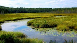
Aerial photo of Regional LandfillRegional Landfill is located in the city of Suffolk, at a site central to both the eastern and western communities of the service area. The site encompasses more than 300 ac. and serves as the location for additional SPSA operations, including yardwaste composting, HHW and used-oil collection, tire shredding, ferrous-metal processing, transfer vehicle maintenance, and landfill gas (LFG) recovery and reuse. The synthetically lined landfill received its first ton of solid waste in l985, and today approximately 44% of the waste managed by SPSA is disposed of at the landfill. This nonprocessible waste is spread, compacted, and covered with a 6-in. layer of soil at the end of each day. Groundwater is regularly monitored through the landfill groundwater monitoring. Facilities include:a ferrous-metals processing plant,a Virginia Recycling Corporation tire processing plant,a ZAPCO LFG-to-energy plant,a Soilex soil remediation facility,an administration/maintenance building,a yardwaste composting facility,an HHW collection facility,a vehicle and equipment wash facility,a leachate pond and pump station,a citizens’ waste drop-off area,a scale house.Approximately 150 ac. of the landfill site are used for actual disposal of solid waste. SPSA recently constructed a 43-ac. landfill cell known as Cell V, which exceeds federal and state regulatory design requirements, and began accepting waste in May 2000. Cells I through IV of the landfill also remain in operation. The existing landfill is expected to have 10-12 years of disposal capacity. SPSA also plans to construct an additional disposal cell, Cell VI, on the existing landfill site, which will likewise add another 10-12 years of active life to the landfill. In anticipation of the area’s disposal needs beyond that point, SPSA is proposing to expand the landfill onto a portion of a 525-ac. parcel adjacent to the existing landfill. The proposed expansion area, Cell VII, occupies 69 ac. in the southernmost third of the site, between the gas pipeline easement and US Route 13/58/460.Design and ConstructionEmployees at the opening of Regional Landfill’s Cell VCells I through IV. Regional Landfill has been a state-of-the-art facility since the Virginia Department of Health issued its initial permit in September 1983. Although this permit preceded the promulgation of the federal Subtitle D regulations and the resulting changes to the state requirements, the facility design included a clay and synthetic liner system with leachate collection piping. The Cell IV construction package included a leachate pretreatment system consisting of a holding lagoon for equalization, an aeration lagoon, and a pumping station/force main for conveying the pretreatment leachate to the Hampton Roads Sanitation District for final disposal. To minimize turbidity in groundwater sampling, SPSA uses QED Well Wizards.Cell V. SPSA began planning the Cell V expansion in 1993. In 1997, all permits had been obtained, but SPSA decided to consider a revision to the Cell V design to an inward gradient system for both economical and environmental reasons. The landfill economics are improved by gaining additional airspace through significant excavation prior to liner placement. SPSA has been able to directly compare the economics of the conventional Cell V design to the inward gradient design. In 1997, bids were received for construction of the conventional design, with a low bid of $8.6 million. The conventional design included 2.1 million tons of waste capacity. Therefore, the liner system cost was $4.05/ton of capacity constructed. The inward gradient design was bid in 1998 and was awarded for a construction cost of only $8.9 million, an increase of only 3.5%. However, the design affords 3.7 million tons of capacity, an increase of 76%. This calculates to a liner system cost of only $2.38/ton of constructed capacity. Viewed incrementally, Cell V afforded 1.6 million tons of waste disposal capacity for only $300,000, equating to only $0.20/ton of capacity gained. In addition, 1.5 million yd.3 of soil was gained from the excavation. Based on historical costs to truck in cover soils, the soil is worth more than $10 million to SPSA.Innovation and Creativity In addition to the innovations of Cell V described in Section 2, SPSA’s Regional Landfill is host to a number of unique solid waste management facilities and practices.Pipe installation for Cell V constructionSoil Remediation. In 1999, SPSA opened a 15,000-ft.2 soil remediation and treatment facility at Regional Landfill. The facility, operated by Soilex Corporation, specializes in treatment and recycling of petroleum-contaminated material. The site receives the majority of the region’s waste materials from oil spills and other emergency response actions. Once treated, the material is used for landfill cover, offsetting the cost of transporting material from off-site.Yardwaste Composting. Yardwaste recycling facilities are located at Regional Landfill. Leaves, grass clippings, and tree trimmings are converted into mulch or composted to produce approximately 80,000 yd.3 of 100% recycled material each year. Mulch and compost are sold to landscapers, nurseries, and residents for use in gardening and lawn care under the trade name Nature’s Blend.Drop-Off Center. A drop-off recycling program was initiated in 1991 for residents not receiving curbside service. Today there are more than 35 drop-off sites located throughout the communities SPSA serves, one of which is at Regional Landfill. Residents may bring recyclables such as newspaper, cardboard, phone books, glass bottles and jars, aluminum cans and foil, steel cans, and household dry-cell batteries. Most drop-off sites are available for residents’ use 24 hours a day.Ferrous-Metal Processing Plant. The ferrous-metal processing plant cleans and presses into nuggets the ferrous metal extracted from the wastestreams at the refuse-derived fuel plant and the power plant. Each month, the plant processes approximately 1,000 tons of material for sale to steel mills. The ferrous-metal processing plant opened in October 1989–only the second facility of its kind in operation in the country. A private contractor operates the facility for SPSA.Tire Shredder. The tire shredder processes approximately 200,000 tires each year received from residents as well as commercial and municipal haulers. Automobile tires are shredded to create fuel for use at the power plant, and truck tires are collected to serve as raw material in the manufacturing of solid-rubber industrial equipment tires. As with the ferrous-metal processing plant, the tire shredder is located at Regional Landfill and operated by a private contractor.LFG/Power Generation. In 1995, SPSA’s landfilled waste became an energy resource to residents of the Tidewater Region. Zahren Alternative Power Corporation (ZAPCO) constructed and operates the nearly $5 million facility, which produces electricity through use of four generator sets (3.2 MW) for sale to Virginia Power. The plant produces enough electricity to power more than 6,000 homes. Broadening its operation, ZAPCO is currently constructing an LFG line to a local industry to provide an additional fuel source for their boilers. Silver Award (Tie)Integrated Solid Waste Management FacilityIn 1989, despite much involvement with an adjoining county government in a joint venture to site a landfill, the City of Bristol, VA (population 18,000), was rapidly running out of airspace in its existing landfill and faced imminent closure.Immediately adjacent to the city’s existing landfill lay the abandoned Vulcan Materials Company limestone quarry. The quarry, with canyonlike dimensions, had recently closed in 1988. Vulcan previously investigated the possibility of using the quarry as a regional landfill and went so far as to initiate a preliminary feasibility/marketing study, but the prospect of successfully permitting a landfill through the Virginia Department of Waste Management seemed remote.Three salient points emerged that led the city back to the Vulcan quarry: (1) the belief that Subtitle D regulations would render small jurisdiction ownership and management of individual landfills prohibitively expensive, opening the door for larger regional facilities; (2) the same regulations were primarily performance-based, thus allowing greater engineering flexibility needed for a landfill development in a rock quarry; and (3) redirecting the jurisdiction’s MSW effort from disposal to transfer with the associated costs and uncertainties was deemed unacceptable. A feasibility study conducted by STS Consultants Ltd. indicated that the quarry landfill was technically viable, and construction began in September 1996. Funding for the landfill construction and start-up operations was provided by a combination of general fund reserves, user tipping fees, and two general obligation bonds. A $3.5 million development grant was also secured from the Tennessee Valley Authority.Design and ConstructionOverall the quarry had dimensions approximately 2,100 ft. long on its north/south axis, 800 ft. wide, and nearly 350 ft. deep, yielding a preexcavated airspace nominally valued at $8 million to $16 million as compared to conventional landfill excavation costs. The quarry was configured as a figure eight with the north and south end separated by a narrowed neck. A development plan for both ends of the quarry provided for the north end to be developed first, followed by the south end. This development scheme provided for unequal phases with nearly three times the volume in the south end versus the north end and a total capacity of 8 million yd.3 This airspace capacity at current filling rates would serve the region’s landfill needs for about 35 years.With a preliminary development scheme in mind, an economic model projected a cost of operations and capital amortization ranging from $12 to $16.50/ton, depending on several operating assumptions. These break-even cost projections assumed that the capital costs could be amortized over the full life of the facility.Early planning determined the quarry to be feasible if (1) it was initially operated as a balefill; (2) the required regulation variances were granted during the permitting process; and (3) a follow-up geotechnical analysis revealed the slope stability concerns were manageable. Baling was considered important so that the MSW was prestressed in advance before disposal to minimize stress, strain, and settlement because of downdrag forces on sidewall liner system.MSW is delivered to the 20,000-ft.2 tipping floor at the transfer station where it is screened, sorted, and blended for smooth baler operation and maximum bale density. In-situ baled waste densities average nearly 1,600 lb./yd.3, with fill depths ranging from 50 to 100 ft.The leachate management system consists of collection piping, a wet-well sump, and a 325-ft.-deep access shaft. About 3.1 million gal. of leachate was managed and treated in 2000, and currently the leachate quality meets all of the pretreatment standards required by the sewer utility. Scrap tires, which are shredded and recycled on-site, are used as fill in the upper portion of the leachate collection blanket drain. The lower part of the leachate collection blanket consists of a 6-in.-thick sand blanket overlain by 1 ft. of noncalcareous aggregate.The LFG management system consists of a horizontal gas collection/vent system installed during the bale placement activities. These gas collection legs are connected to a header to vent gas and minimize gas-pressure development. The headers and drop-pipe risers are monitored for LFG constituent concentrations and pressure.As the lowest dewatering point within several miles, the quarry serves as a groundwater sink for the region. Upgradient groundwater monitoring wells are located around the quarry rim. These wells determine the natural background groundwater quality. Each of these drain legs is designed to be permanently saturated below the base liner. The backpressure in each drain leg may also be varied by adjusting the weir levels in the access shaft sump on an as-needed basis to control groundwater flows below the baseliner system.The baling/transfer station is designed for material handling efficiency and consists of a two-level baling and tipping floor. A horizontal conveyor moves the MSW refuse from a conveyor pit on the upper tipping floor to the baling hopper below and is compacted in a two-stage baler. Bale loading, cleanup, and maintenance occur on the lower baling floor, where bales are loaded with forklifts and then transported via rolloff truck to the disposal location in the quarry landfill. The bales are then unloaded and placed in blocklike walls/wall faces and later covered with an alternative daily cover (ADC).The facility currently serves a four-state region consisting of regional communities and solid waste management districts, as well as private haulers mostly within a 100-mi. radius. Bristol has managed both the operations and marketing of the quarry landfill and has increased the daily MSW receipts to average more than 600 tpd in a three-year period since start-up. MSW growth has been almost 200% alone in the last two years. Even greater growth has been experienced with nonbaleable wastes. The city currently offers an advertised $25.50/ton MSW tipping fee. Volume discounts are offered under service bids or negotiated contracts for larger-volume and longer-duration contracts. The quarry landfill currently ranks as the local low-cost provider.Annual quarry landfill revenue currently approaches $4 million per year, which covers the $1.75 million annual cost of operations. Modest revenue is also earned in other operations. The city maintains financial assurance in the amount of $4.3 million for estimated closure costs and $3.4 million for the estimated postclosure care costs under the terms of the quarry landfill permit. Innovation and CreativityThe sidewall liner system was created out of a laminated sandwich of geosynthetics consisting of a 16-oz. needle-punch geotextile overlain with a 60-mil, single-sided, textured HDPE geomembrane overlain by a double-sided, trilinear geocomposite drain. These three geosynthetics act together to create a barrier system to control water flow on both the front and back sides of the geomembrane, to cushion both sides of the geomembrane from damage, and to provide a preferred friction slip-surface between the geomembrane and the buffer/structural fill placed inboard of the composite drainage layer, if necessary. The sidewall liner also acts as a rockfall mitigation system.Tajiguas LandfillTajiguas Landfill is the only landfill serving the south coast of Santa Barbara County, CA, which in 2000 had a population of approximately 262,200. Typically, 700-800 tpd are delivered to the site by an average of 75 vehicles, primarily commercial, as Tajiguas does not accept self-hauls except from immediate neighbors.Santa Barbara County’s recycling logo (above) and solid waste staff (below)The landfill is situated in a small, confined, south-facing coastal canyon 26 mi. west of the city of Santa Barbara. In its present (January 2001) configuration, the landfill has nine 40-ft.-high, generally south-facing benches that abut the east side of the canyon and partially abut the west side of the canyon. South of the fill area, a cutoff trench extending into bedrock intercepts subsurface water flow and some piped discharge so there is no offsite subsurface water discharge.Through the early 1990s, waste cells were routinely constructed behind earthen berms measuring between 15 and 50 ft. thick. The area method of disposal was used, requiring refuse-hauling vehicles to travel on a landfill access road over previously buried refuse to the disposal area. Ridges were constructed on the top deck in an east-westerly direction, dividing the top-deck drainage pattern into two parts. As additional waste lifts were placed, a slope was built onto the interim surface to promote drainage. By the mid-1990s, imminent expansion beyond previous waste areas as defined in 1989 required that a liner be installed along the east side of the landfill on the eastern canyon wall.In 1999, a new configuration was designed to take advantage of a considerable amount of permitted airspace volume of the outside faces of the landfill. A permit was obtained to excavate parts of the thick soil retaining berms of the lower benches (built in the 1960s) and to emplace new refuse fill at a steeper angle (2:1 vs. 3:1). This phase of construction was referred to as the Benchfill Plan that began in November 1999 and is projected to provide approximately six years of additional landfill permitted airspace.To prevent the generation of leachate, stormwater is diverted around the active landfill via a 48-in.-diameter subsurface culvert that drains the lower in-channel basin and generally follows the western perimeter of the landfill. Runoff is transmitted via a concrete drainage outlet structure south of the toe of the landfill, leading to a natural water course just east of the entrance road. From here it travels about a mile, in part under the freeway, and is discharged into the ocean.In California the average tipping fee in 2000 was $39.62 and the highest was $85, according to a survey published in 2001 by the California Integrated Waste Management Board. Tajiguas’s integrated tip fee of $48 helps fund programs critical to increasing the longevity of landfill. Vehicles check in at the scale house, where they are weighed on a computerized scale using Compu-Weigh and Weigh Station software. The vehicles are spot-checked for hazardous materials by scale-house personnel, and records of the daily wastestream from private haulers and county-operated transfer trucks are compiled daily. In addition to screening for hazardous materials, checkers try to identify valuable recyclable loads that can be redirected to the South Coast Transfer Station for recycling.At the end of each operating day, if the newly placed waste layer is not yet to grade, it is covered with 6 in. of clean soil from the soil borrow area or an ADC. The cell is constructed, and cover is placed to promote positive drainage in the area. The next working day, the process is repeated. Approved ADCs at Tajiguas Landfill include greenwaste, foam, and tarps. The use of an ADC can save from 125 to 150 yd.3 of airspace a day. The use of a tarp ADC has been found to conserve the greatest amount of airspace and therefore is used more often.Typical waste cell dimensions are approximately 17 ft. high, 125 ft. wide and 20 ft. deep. As often as possible, the county surveyor’s office helps establish the line where waste cells start and finish using a global positioning system unit. Waste cell density is tracked via aerial topographic photos taken approximately every six months and then calculated against how much airspace is available.Immediate dust control at the site consists of the daily spraying of water by water truck(s) on roads and in active working areas. Preventative control measures include applying soil stabilizer such as Soil Sement, a liquid binder that hardens the soil surface, forming a crust, making it resistant to wind erosion for months at a time; hydroseeding on bare slope areas to bind soil and reduce blowing dust areas; applying wood-chip mulch (generated at the landfill) on borrow areas not in use for the season; removing loose earth from haul roads and restricting travel on unpaved roads; and capping frequently used haul roads with asphalt.Cell construction is planned and sequenced to minimize exposure to prevailing winds during winter and summer and to orient, when possible, the working face to shelter waste unloading areas from winds blowing north-south. During severe wind events, there is a contingency plan for redirecting waste bound for the landfill to the transfer station. Standby operations personnel are available to staff the landfill on Sundays or holidays if large flows of stormwater runoff occur. Other controls include minimization of the working-face size, immediate and increased compaction of waste, and placement of earth berms around the active area.Three leachate collection and removal systems operate at Tajiguas. The first system is a subsurface collection trench located in the narrowest part of the canyon downstream of the landfill. The second system is part of a composite liner located on the eastern side of the landfill. The liner and leachate collection system consists of a 60-mil-thick plastic liner membrane, a geosynthetic clay layer (GCL), and associated collection and drainage piping. The third system consists of three horizontal wells–each 200 ft. long–constructed at a level between the toe of the landfill mass and the first bench. Liquid collected from these wells is drained by gravity to a 4,300-gal., aboveground, double-contained storage tank located near the wellheads. A GCL system covers an area of approximately 300,000 ft.2 along the eastern slope of the canyon. The GCL was installed over the subgrade and was in turn overlain by a flexible membrane liner (FML) made of high-density polyethylene (HDPE). On slope areas, the FML is textured on one side, with the textured side placed down and in contact with the GCL to prevent slippage. The FML on slope areas is further overlain by 16-oz. nonwoven geotextile material, which in turn is overlain with scrim reinforced protective plastic in areas not covered with the protective cover/operations layer. On relatively flat-bottom areas, the HDPE membrane is textured on both sides and is overlain by a 12-in.-thick gravel layer, an 8-oz. nonwoven geotextile, and a 24-in.-thick operations layer composed of onsite screened material with a maximum 1-in.-diameter particle size.The Tajiguas LFG-to-energy project, a partnership between the Santa Barbara County Department of Public Works and NEO Inc., resulted in the installation in 1998 of the active LFG collection and disposal system at the Tajiguas Landfill. Designed to reduce surface emissions of LFG while concurrently meeting regulatory requirements of EPA’s New Source Performance Standards, the LFG system at Tajiguas consists of a network of vertical LFG extraction wells, laterals and headers that convey the LFG to the cogeneration plant and flare. Bronze Award (Tie)Brea Olinda Alpha LandfillOlinda Alpha Landfill (OAL) is a Class III Sanitary Landfill located in Orange County, CA, adjacent to the city of Brea. It is located on a 562-ac. county-owned property, of which 420 ac. are used for waste disposal. OAL accepts only nonhazardous MSW. The service area of the landfill includes the cities of Anaheim, Brea, Fullerton, Garden Grove, La Habra, Orange, Placentia, Yorba Linda, and several unincorporated Orange County communities that deliver solid waste for disposal under long-term contracts for $22/ton disposed. Three privately owned transfer/MRFs process solid waste for the cities and deliver residual waste and waste self-hauled to their facilities to Olinda under the contract rate. Approximately 12% of the waste disposed is delivered by self-haul to the landfill at a disposal rate equivalent to $27/ton. In addition to Orange County waste, OAL also accepts imported waste from surrounding communities in Los Angeles, Riverside, and San Bernardino Counties.The landfill is operated by the county’s Integrated Waste Management Department (IWMD). OAL is the fourth-largest landfill in California based on a total annual 1999 disposal of 1.9 million tons. The landfill’s daily maximum permitted disposal capacity is 8,000 tons. The site receives approximately 6,300 tpd. The ultimate site capacity is 123.1 million yd.3
Operational since 1960, the landfill is composed of two canyons, Olinda and Olinda Alpha, which were initially separately permitted landfills. Excavation of the central ridge dividing the canyons was completed in October 2000 as part of a 1992 plan to provide necessary disposal capacity. By agreement between the County and City of Brea, OAL is scheduled to close in 2013; however, at the present fill rate and using best management practices, it is estimated that the active life could be