In recent years, materials recovery facilities designed for construction-and demolition-debris (C&D) have rapidly emerged as a major trend by communities to increase their overall landfill diversion rates.
C&D is the material generated from the demolition of buildings and other similar civil works infrastructure, the vegetation from land clearing, including rocks and soil, and the residual material from the construction of a structure. Thus, specific types of materials could include:
- Metals-reinforcing steel, steel shapes, wire, cans, conduit, etc.
- Concrete, brick, stone, tile, rocks, and soil
- Plastics-bottles, buckets, containers, drums, wrapping, etc.
- Rope
- Paper and cardboard
- Wood and dimensional lumber, pallets
- Ceramics
- Gypsum drywall
- Plaster
- Asphalt
- Rubber
- Foam, insulation, packing, etc.
- Adhesive, glues, paint, etc.
- Vegetation
C&D waste presents unique recycling challenges because of its nature. It is inherently a relatively dry waste that, when agitated and processed, produces a lot of dust. Materials can be combined and intertwined in a way that makes separating them difficult. Most of the material is bulky, heavy, and/or abrasive. It can cause extensive wear and tear on machinery and can also be a safety hazard to plant workers if proper controls are not observed.
Recycling of parts of demolished buildings has been conducted since the turn of the 20th century. The reuse of steel beams and columns in automobile bodies is one example, as is the reuse of bricks. However, several factors that emerged in the 1980s have stimulated the growth of C&D recycling into a large and varied sector of industry encompassing many other materials. These factors include:
- Sustained cycles of significant new construction in many major cities
- The development of relatively inexpensive C&D landfills to take residual material left over from the recycling process
- The emergence of other markets for recycled materials, a result of the increased use of alternative feedstock for energy production
- The development and refinement of automated machinery to process C&D derived from municipal wastestreams
- The development of formal “green” building development initiatives that advocate recycling of municipal waste
Most C&D recycling operations in the past relied mostly on manual labor to sort materials. The current generation of these recycling facilities can consistently remove as much as 90%, or more, of the recyclable material from the wastestream, using mostly automated machinery, resulting in a very low production of residual material left over for landfilling. For specific tasks where the benefit/cost for replacing a worker with a machine can be as effective, manual labor is not economically attractive.
Waste Processing and Recycling Operations
Most of the automated machinery used in current C&D plants has been derived from the basic materials mining industry and modified for the commercial market. In some cases, new equipment has been designed specifically for municipal C&D materials. The planning and design of a recycling plant is based on many factors that include the following:
- Volume of C&D material projected to be managed over the next five to 10 years
- The reuse markets that exist or can be developed for recycled materials and the revenue potential
- Location, size, and availability of property relative to the market being served
- Development and operating budget (this includes the use of manual labor and automated equipment)
The primary goal in a C&D recycling facility is to be highly efficient, meaning extract as much of the valuable material as possible while producing the lowest amount of residual material. For a privately owned recycling business, this is strictly an economic issue. When the total cost of processing C&D waste to remove a specific material exceeds the revenue generated from the sale of that material to the reuse market, then the material is not valuable from a recycling standpoint. Accordingly, the disposal of residual material in the landfill is a cost to the plant operator, so reducing residual disposal costs enhances the net revenue from the sale of recyclable materials.
The economic “equation” for a municipally owned/operated facility is a little different, in that this would be a public service, and demonstrating a healthy “profit” is not the prime focus. However, the process efficiency goal is still the same whether the facility is private or publicly owned.
What is determined to be a valuable material can change over time as the market and, more specifically, the prices paid change for various materials. Thus, the recycling plant must have some flexibility built into the separation process and the overall “floor plan layout” in order to be able to process a variety of valuable material and be responsive to changing markets.
Processing Schemes
Design of a processing system for C&D waste follows an approach that, in general, encompasses the following basic principles listed below, starting at the waste tipping area, progressing through mechanized and manual separation then to the temporary storage areas for each targeted material. Some or all of these may be incorporated depending on the factors previously mentioned. Keep in mind there are many different technologies and equipment that can accomplish your goals and we could not cover them all. We have only described herein a few proven techniques.
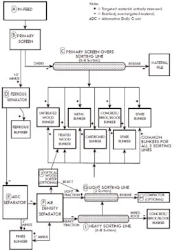
A schematic illustrating the basic material separation and flow processes is provided in Figure 1. Following along with that exhibit, the descriptions below correspond to the letters designating certain features on the exhibit:
- Initial agitation to start to separate the mix of material to improve productivity of downstream processing operations (B)
- Separation of smaller material from larger material. This split usually is around an approximate diameter of 8 inches to 12 inches (20 to 30 cm) (B).
- Separation of ferrous metal to prevent damage to downstream equipment (D)
- Separation of small stones, glass pieces, sand, and grit to reduce wear and tear on downstream equipment (E)
- Separation of light, “two-dimensional” materials (e.g., paper, cardboard, and plastic film products) from smaller and/or denser “three-dimensional” materials (e.g., small containers, bottles, other objects, pieces of nonferrous metal, sticks of wood) (F)
- Separation of wood/lumber, either with optical machinery (J) or water bath
- Separation of nonferrous metal, other wood, concrete pieces, asphalt, drywall, etc. This is usually done manually on a “picking line” conveyor system (described below) (C, G, and I).
Bulk Material Recycling
The recycling of large pieces of concrete, steel-reinforced concrete, and asphalt is a process that requires specially designed, heavy-duty machines. Concrete and asphalt recycling is either done at a permanent site, or a mobile processing system can travel to the specific site if there is an extensive volume of material and bulky and heavy pieces that would be cost prohibitive to transport to the recycler. These machines can remove and recycle the steel reinforcing bars and crush the remaining concrete and aggregate to specific sizes. A bulk operation may be separate from an operation receiving a mixed wastestream with smaller pieces because of the land area required for the storage piles at the former operations.
A somewhat unique activity that is common in south Florida is the filling of rock-pit lakes with certain C&D material considered to be “clean debris.” Clean debris is clean concrete, brick, soil, and rocks. Rock-pit lakes are very common in the region and are excavated to obtain the limestone, which is a popular and inexpensive source for concrete aggregate and for use in road subgrade. Later, after the quarry operation moves away, some of the lakes are back-filled with clean debris to make buildable ground.
Screening Operations
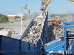
Finger screen-C&D waste is often a clump of different sizes and types of materials intertwined together. These clumps must be separated at the front end of the process in order to make the separation and removal of the specific material as efficient as possible in downstream operations and to reduce the potential for downstream machinery to become clogged.
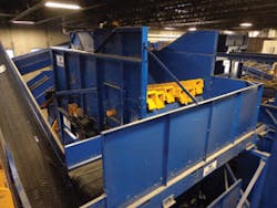
A popular and effective device known as a finger screen is often used for this purpose. A finger screen is a heavily built, mechanized conveyor that uses an articulated, oscillating floor to break up the waste clumps. The waste material is fed into one end and the combination of oscillating motion, and the downward slope of the conveyor induces the waste to move forward and at the same time start to separate (Figure 2).
Figure 2. Vibrating finger screen
At the downstream end of the screen, another feature can provide a rough separation of waste by size and density. If this division is desired, the conveyor floor has an opening in which smaller and denser materials (e.g., stones, wood, and metal pieces, etc.) fall through the opening and are dropped onto another conveyor that takes them to another sorting process. Lighter, flatter, and/or bulkier materials (e.g., cardboard, paper, plywood, plastic film) are carried off the end of the screen conveyor and into the next piece of sorting equipment.
Trommel screen-A trommel screen can be used to accept the material from a finger screen. If no size and density separation occurred on the finger screen, then the trommel can be used for this purpose. A trommel is a device that contains a hollow perforated tube through which the waste moves. The trommel tube is perforated along its length and its circumference with holes of a specific diameter. The tube is angled similarly to the finger screen and is slowly turned on rollers by a motor. As the waste moves through the tube, the rotating action and downward slope moves the materials forward where they encounter the perforations. Pieces of waste smaller than the perforations (known as unders) will fall through the holes and onto a conveyor that will take that material to another sorting process. The larger pieces of material (known as the overs) will move through the trommel and onto the next sorting process.
Star gear screen-Another mechanized device used to separate waste into two size fractions is the star gear screen. A star gear is a conveyor that contains multiple rows of gears affixed to rotating axles. Each axle contains multiple gears spaced at precise intervals along the axle. The spacing of the gears is designed to control the separation of material. As waste material moves into the upstream end of the screen, it is propelled forward by the rotating gear assemblies. As the material moves over the gears, pieces that are more dense and that are smaller than the opening between the gears fall though opening. These may include stones, pieces of wood, metal, plastic, brick, and similar material. Those pieces (the unders) are collected by another conveyor and taken for further sorting or disposal. Lighter pieces that are larger than the opening (the overs) continue to move along the conveyor, essentially floating over the gears to the downstream end, where they flow into the next process. Overs may include cardboard, other papers, pieces of lumber, drywall, plastic film, and similar materials.
Ferrous Metal Separation and Removal
If large amounts of heavy ferrous metal objects are anticipated in the wastestream, then a device known as an overhead magnet is used to remove them from the other wastes. This device is essentially a large industrial magnet surrounded by a continuous looped conveyor belt. The entire device is suspended on a structural frame positioned perpendicular (at a 90-degree angle) above a conventional conveyor belt. Ferrous objects on the conventional conveyor passing under the energized magnet are pulled from the belt onto the magnet’s moving belt and are swept away from the lower conveyor. As the looped belt passes out of the magnetized zone, the object is released and falls into a container for removal.
Other configurations of magnets are available for removal of such smaller and lighter types of ferrous waste as metal cans. These magnets, known as pulley head magnets, can be located within the end rotating pulley system of a conventional conveyor belt system. These magnets operate on a similar principle to the overhead magnet. Cans on the conveyor belt passing over the magnet are retained on the belt as it travels around the pulley to a point almost directly under the belt where the magnetic field ends. At that point the can falls off the belt and into a container. Nonferrous material will flow off the end of the belt and with the help of the belts momentum, will take a trajectory away from the conveyor into a separate container.
Heavy and Light Material Separation
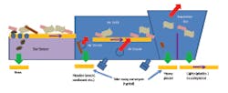
De-stoner/air knife-Separation of such light, “two-dimensional” materials as paper, textile plastic film, aluminum, and pieces of cardboard from heavier, bulkier materials can be accomplished in an automated device called a de-stoner/air knife. Figure 3 shows a schematic cross-section through a unit with two air knifes. This unit uses directional air currents and a vibratory motion to stratify and separate lighter material from heavier material. The unit is mounted on heavy coil springs to reduce the transmission of vibration to the ground.
of Destoner/airknife
Following along on this exhibit, the waste is fed in from a star gear screen and immediately encounters a gap in the air knife through which high-velocity but low-pressure air is flowing. The airflow is provided by a standard centrifugal blower. This flow of air blows the lighter and two-dimensional materials up and toward the downstream conveyor. The heavier and bulkier materials, including small stones and pieces of glass and metal, are unaffected by the air current, and fall through the gap onto a take-away conveyor. Thus, the designation as a de-stoner.
As the lighter materials are conveyed to the end of the air knife, there is another high-velocity, low-pressure air stream directed through the conveyor. This final current of air separates the very light material (mostly plastics and light paper) from other denser bulkier material. The lighter material, with a relatively large cross-sectional area, is carried to the far end of the collection bin, while the denser, more compact material does not travel as far and drops into the bin directly at the end of the conveyor. All air is exhausted out the top of the air box. If a hood is not used over the final air discharge to capture the light product, then a grate or similar screen is used to deflect light material into the air box end bin.
Exhaust air can be captured and rerouted back to the blowers to increase efficiency and reduce discharge of dust to the environment to near zero. This feature is recommended when the unit is used inside a building and outside where migrating dust could pose a nuisance to other operations or adjacent businesses.
Optical sorter-The use of automated machinery employing “electronic eyes” to assist in separating materials has become increasingly popular. In many cases the increased efficiency and higher purity of the targeted material provides a positive benefit/cost ratio as compared with traditional manual methods. The function of the equipment is based on the principle that all solid materials have a unique surface “signature” that reflects and absorbs light rays in varying amounts.
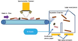
Figure 4 shows a general cross-section of an optical sorter than can be used to separate out large wood pieces.
Following along on this exhibit, as the waste material enters from the conveyor and passes under the control unit, a bright light illuminates the materials. A sophisticated instrument called a spectrometer imbedded in these machines “reads” the reflected light from the materials and, through a computerized interface tuned to see wood product, actuates a compressed-air device that sends a blast of air channeled by the computer program to specific multiple ports positioned across the end of the conveyor belt. As the materials pass over the ports, the ports that have been activated will discharge a blast of air under the material. The air ejects larger wood pieces to a receiving hopper on the far end of the machine, while non-wood material simply rolls off the end of the conveyor belt into a separate hopper.
A vibrating pan feed conveyor is often used to feed the optical sorter. This type of conveyor will increase the effectiveness of the optical sorter by flattening out and separating the materials before they enter the electronic eye detection zone of the sorter.
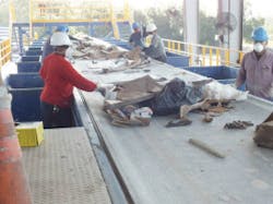
Picking (sorting) line-Some separation of materials is still best achieved with manual labor. The picking line, or sorting line, is a mostly manual work station that is very common in C&D recycling facilities. Picking lines are used for removal of many potentially valuable recyclable materials, including but not limited to flat pieces of wood, nonferrous metals, asphalt and concrete pieces, and cardboard. A picking line is typically a long and narrow steel work platform elevated at least 10 feet or more above the normal working floor (Figure 5). Under the platform, steel or concrete walls form side-by-side bunkers and are used to provide additional platform support. Each bunker is dedicated to temporary storage of a specific material.
Figure 5. Semi-automated picking/sorting line
One or more conveyors are mounted on the platform, parallel to its length, and workers stand along the length of the conveyor, usually on both sides. The conveyor is set at a fixed height so that workers have a comfortable arm reach to remove material from the moving belt. Conveyor belt widths can vary from 30 inches to approximately 72 inches in width, the maximum practical that allows a comfortable reach from either side. Workers are typically spaced about 6 to 8 feet apart. Located between each worker is a steel chute whose bottom is open through the platform floor.
Each worker is assigned to remove (i.e., pick) a specific material. As the conveyor moves material along, the workers pick their targeted material off the belt and drop it through the chute, where the material falls into a storage bunker. This is termed a positive sort. Any materials that are not picked from the conveyor are assumed to be of no recycling value or not practical to segregate and are allowed to flow off the end of the belt into an end bunker. This is termed the negative sort material, or alternately where the contaminant material is selected to be removed from the targeted material.
Periodically the bunkers will be unloaded and the materials taken away for final recycling/reuse or disposal. Bunkers can have mechanized unloading systems or be unloaded with a front-end loader.
Dust Control
The processing of C&D waste typically generates a significant amount of dust. Most of the materials in C&D are inherently dry, and when they are agitated in the various processing operations, dust particles (actually the minute pieces of some of the materials) are released into the air. Dust particles from a C&D operation can range in size from around 100 microns (concrete dust) up to 1,000 microns (textile dust).
C&D processing operations outdoors and inside a building can create a nuisance to neighbors with fugitive dust generation if it is not controlled properly. Constant -uncontrolled dust can also be a health -hazard to workers.
The primary sources of dust can include the following:
- Tipping floor
- Finger screen
- Air knife
- Storage piles (especially for residual “fine” materials)
- Recycled material load-out
Dust control is mostly science (and partly an art) and too extensive a topic to cover completely here. However, fugitive dust is probably the most prevalent problem with C&D processing. Dust controls can take many forms, from basic static screening material to misting devices and mechanized filtering systems. The most common system for waste operations, the misting system, is discussed herein.
Wet systems-Dust is commonly controlled using wet spray systems where enclosing the material area is impractical. Wet systems can be applied for prevention of dust and suppression of dust. Prevention is done by applying a wet mist directly to the material to reduce liberation of dust. Suppression is applying a mist to the air around the material once it is agitated and dust is released. The type of misting system depends on the situation. Many C&D recycling operations may require both. Recycling facilities are particularly sensitive to the correct dust control. If too much water is applied, the materials may stick together and significantly reduce the effectiveness of downstream separation activities.
Effective dust control depends on many factors, including dust particle size, wind effects, freezing temperatures, nozzle types, nozzle spray patterns, spray locations, available water pressure, use of compressed air, and use of surface wetting agents (surfactants), to name a few. The droplet size produced from the system must be compatible with the dust particle size, or removal is reduced. Dust control is best left to companies that are experts in the design and operation of these systems in waste handling operations.
Vibration-A brief discussion on vibration is in order. The type of waste processing systems described herein contain several pieces of heavy oscillating equipment, as well as a significant amount of rotating machinery in general. These systems produce steady-state (continuous) vibration, and impact (isolated) vibration. Steady-state vibration occurs during normal running operation. Impact vibration can occur when the equipment is started and stopped or a unusually heavy material is dropped into the machinery. The location of such a system should consider the potential for this equipment to transmit these vibrations to the ground, despite the vibration-dampening systems designed into most of the equipment. Vibration also results from waste-tipping operations and load-out of recyclable materials. A significant buffer zone is generally needed between the equipment and the property line to allow the ground vibration to dissipate to a background level.
Many municipalities have a standard for industrial zones that sets the maximum limit on steady-state and impact vibration. Without an adequate buffer width, vibration can be transmitted to adjacent properties where it can become a significant annoyance. The distance and strength over which vibration can be transmitted is contingent on many factors, including soil type, moisture content, frequency of vibration (i.e., number of oscillations per unit time), and others. It is recommended you consult the equipment manufacturer for guidance on a buffer distance. A buffer distance of 200 feet would be considered a good starting minimum with competent soil, a larger distance is preferred if available.
Recycling Byproducts
The processing of C&D waste with a certain combination of equipment can result in a residual by-product known as recovered screen material (RSM). RSM looks similar to soil and is mostly the combined residual of some actual soil and minute pieces of friable waste that may include, drywall, paint, plaster, asphalt shingle grit, pieces of grout, cement, brick, glass, and plastic.
Some recycling companies have experimented with developing this product for use as a substitute where lighter, load-bearing, natural soil fill is acceptable. For example, in shaping contours on a golf course, filling residential lots up to flood criteria, and similar uses where natural soil is typically used. Although some regulatory agencies have approved its use in certain conditions after an extensive chemical testing program, and it has been marketed with some limited success, extra caution is warranted. Some RSM has been found to be contaminated with chemicals that, although they are native to the virgin materials, are of environmental concern because of their potential to leach out of the RSM. These chemicals include polynuclear aromatic hydrocarbons (PAHs), lead, and arsenic.
RSM is ground-up residual from many materials. As a result, the surface area of the individual particles is increased, which can then increase their solubility when wetted. The increased solubility may result in leaching of the chemical, which can result in contamination of the natural soil and groundwater. Common materials containing these contaminants include asphalt roofing shingles (PAHs), paint (lead), and treated wood (arsenic). Removal of the offending materials from the wastestream before they go through the separation process so they do not end up in the RSM is a time-consuming and expensive process that requires constant vigilance on the part of the operator. It is recommended to steer clear of RSM.Randy’s Environmental Services had a challenge on its hands as it prepared to equip a MRF that would be accepting a wide variety of materials.
Jim Wollschlager and Mark Stoltman from Randy’s Environmental Services conducted their research, and one vendor began to emerge as their favorite. “We toured several MRFs around the country and felt the Machinex installations were well laid out and were able to move the material without jams and bottlenecks,” says Stoltman.
Randy’s gave Machinex the challenge to team up with the company in designing a system that would meet its needs and allow for flexibility in the future. The system provider also worked in partnership with Randy’s to design a system that allowed recovering 100% of those bags.
The Blue Bag Organics program was just one component of a wider stream that the Randy’s MRF would have to handle.
The primary focus at Randy’s was to be able to process both residential single-stream material as well as municipal solid waste (MSW) because of the Organics Blue Bag program.
A variety of screens would be necessary, although Machinex had an alternative technology that turned out to be a key component. Conventional screening technologies appeared more labor and maintenance intensive, specifically because of the film and bags. The Mach Ballistic answered the client concerns and proved to be a very efficient means to separate the three fractions of fiber, containers, and fines. This versatile equipment ensures that different material types can be processed within a single system. Also, it has the advantage that the plastic film doesn’t wrap around the disks.
Chris Hawn, Machinex North American sales manager, says the Machinex team took on several challenges to offer solutions for the MRF. Mach Ballistic was the right solution for several reasons. “No conventional system, whether for MSW or single-stream, was really efficient for this application, so Machinex designed a hybrid system that includes a trommel, two Mach Ballistic separators, and mechanical separation for containers.”
The combination of sorting technologies creates a great system for efficient sorting of both types of material.
After operating and observing the system in place for nearly a year, Wollschlager agrees. “The system has worked well and proved to be very dependable,” he states.
Customizing a MRF
MRF: Randy’s Environmental Services, Delano, MN.
Capacity: 25 tons per hour of MSW; 12 tons per hour of residential single-stream recyclables
Equipment: Two Mach Ballistic separators, trommel screen, additional mechanical separation equipment
Process: In addition to MSW and single-stream recyclables, the MRF accepts organics in compostable blue bags that residents place in their garbage bins with other waste. At the MRF, the blue bags are not open, and the sorters remove them at a presort station and place them into a bunker, after which they go to a composting platform.
