Green Stormwater Infrastructure on an Urban Arterial
On March 6, 2013, the mayor of Seattle announced a new goal: to manage 700 million gallons of stormwater annually with green stormwater infrastructure (GSI) by the year 2025. Due to the topographic conditions in Seattle, with many landslide-prone slopes, and the geologic conditions, with many areas underlain by a low-permeability layer of soil (i.e., glacial till or hardpan), the goal of handling approximately 70% of the rainfall volume with GSI practices appears ambitious. Regardless, this initiative underscores the emphasis that the city is placing on the use of green stormwater practices for treating and controlling runoff.
The city of Seattle has been on the forefront of low-impact-development (LID) techniques utilizing green infrastructure since the early 2000s when it began implementing natural drainage system (NDS) designs in areas discharging to sensitive and degraded creeks. Seattle’s Street Edge Alternatives (SEA Streets) and “110th Cascade” projects employed creative and effective methods of reducing impervious areas and providing natural water-quality and detention benefits. After more than a decade of collecting monitoring data on these projects, study results have shown that they reduced runoff volumes by more than 98% during the rainy season. Now the city is looking to expand these successes to projects throughout the city wherever it is possible.
Not only is GSI helping Seattle address the runoff impacts from development, it also serves to bring back elements important to maintaining the hydrologic cycle. The requirement for utilizing GSI on projects with more than 2,000 square feet of new or replaced impervious surface was added to the city’s 2009 stormwater code with the intent to “reduce the effects of development on receiving water temperature and move the city towards re-establishing lost vegetation in fully developed areas.”
The difficulty in implementing GSI on projects where site conditions are less than ideal was recognized, and the city qualified its GSI requirement with the phrase “to the maximum extent feasible” (MEF). The Seattle Stormwater Manual defines MEF as follows: “The requirement is to be fully implemented, constrained only by the physical limitations of the site, practical considerations of engineering design, and reasonable considerations of financial costs and environmental impacts.”
AAC North 105th Street and Northgate Way Project: GSI to the MEF
The purpose of the project is to improve the four-lane corridor along North 105th Street and North/Northeast Northgate Way from Greenwood Ave North to Lake City Way Northeast. Improvements will include 1.4 miles of roadway repaving, new sidewalks and curb ramps, drainage improvements, street lighting and traffic signals, and intelligent transportation system components. In late 2011, the Seattle Department of Transportation (SDOT) selected Parsons Brinckerhoff to design the drainage system improvements for the project. All other design services for the project were performed in-house by SDOT staff.
The professional drainage design services provided by Parsons Brinckerhoff included drainage reports, plans, profiles, details, special provision specifications, construction cost estimates, and construction support services. The project was advertised for construction in the first quarter of 2013, and construction began in July 2013. The construction bid for the project was $9.1 million with approximately 25% of the total construction costs related to the drainage improvements. The project lies within separated sewer drainage basins in north Seattle. Two of the basins discharge to creek basins, Thornton and Pipers creeks, and a third lies within the Densmore Lake Basin. Although the project does not add any new impervious surface area, it involves replacing roadway and sidewalk surfaces well above the “trigger” amounts requiring flow control and treatment. All three basins required both stormwater flow control and water-quality treatment. The project also triggered the requirement to utilize GSI to the MEF with a goal of mitigating 100% of the downstream impacts from the replaced impervious surfaces. In the event that less than the 100% goal is realized, documentation must be provided to justify the lower mitigation percentage. Allowable justifications are engineering limitations (low infiltration rates, flooding potential), physical limitations (utility conflicts, steep slopes, intended use of right of way), and excessive financial costs (additional cost estimates are required).
Evaluating the Feasibility of GSI
The project was very constrainedon what GSI best management practices (BMPs) could be used to meet the 100% mitigation goal.The right of way was very narrow and allowed for only 5-foot sidewalks and 3-foot planter strips along much ofthe project.
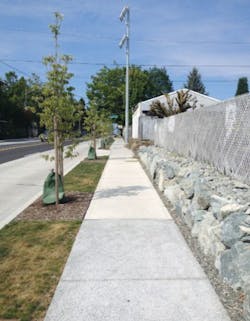
Although the drainage design team worked to minimize impacts to trees during design, a walkthrough of the project with the city’s arborist at the 90% complete stage was made to identify any additional modifications that could be made to the design to minimize impacts to trees. This walkthrough identified several modifications to the drainage design to be made to reduce the risk of root damage from excavation. The retention of the existing trees was used to partially meet the city’s GSI requirement. Additionally, new trees were added, mitigating up to 50 square feet of impervious surface per tree (Figure 1).
Infiltration GSI BMPs were not considered feasible because the planter strips are too narrow, approximately 3 feet in width, to allow for bioretention planters. The city does not consider belowgrade infiltration systems to be a GSI BMP, and therefore buried infiltration systems were not used.
As an impervious surface reduction method, porous concrete was used where allowed by city code—only on sidewalks having less than a 5% longitudinal slope. Figure 1 shows the transition between a porous concrete section of sidewalk and concrete sidewalk. Around 20% of the concrete sidewalks added by the project met this code requirement. Approximately 11,000 square feet of impervious surfaces were mitigated through existing and new tree canopy, and 10,750 square feet of impervious surfaces were mitigated through the use of porous concrete surfaces. This resulted in 9.5% of the 5.2 acres of new plus replaced impervious surfaces being mitigated using GSI. GSI to the MEF documentation, included in the stormwater technical information report prepared for city approval, demonstrated that there were no other GSI BMPs that were feasible for the project.
Project Flow Control Requirements
The city code requires that a continuous hydrologic model be performed to confirm that the flow control targets are met even if the project had achieved the 100% mitigation of the new plus replaced impervious surfaces using GSI BMPs. In areas with low permeability, as is the case in most of Seattle, additional flow control would typically still be required. The project achieved only minor reduction in the required flow control volumes using GSI BMPs, and the project used five stormwater detention pipes, ranging in diameter from 60 to 84 inches, to meet the remaining flow control requirement.
The challenge of sizing the stormwater detention facilities for the creek basins was in meeting the very restrictive release rate requirements and minimum orifice size. The requirement was for developed runoff to match a predeveloped condition modeled as a pasture and that the minimum orifice size in the flow control structure be 1/2 inch in diameter to reduce the risk of clogging. This results in the need for relatively long detention pipes to provide the required detention volume without having the additional hydraulic head that a larger-diameter pipe would place on the 1/2-inch orifice.
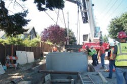
One of the detention pipes was approximately 600 feet long in order to provide the required volume without exceeding the allowable flow rates by increasing the head on the 1/2-inch orifice. The 600-foot-long, 48-inch pipe was designed to be placed under or over 12 different utilities including a water main, sewer main, and a 16-inch-high pressure gas main, and it was sandwiched in a 12-foot-wide corridor with an existing storm line on one side, and the right of way line on the other. Additionally, the city does not allow detention pipes to be reduced in size as they enter a maintenance hole, as some jurisdictions allow. This resulted in maintenance holes up to 10 feet in diameter being required (Figure 2). The use of three-dimensional modeling was essential in locating the detention pipes in such a heavily congested utility corridor.
Project Treatment Requirements
Because the amount of replaced pollution-generating impervious surface in all three drainage basins exceeded 5,000 square feet, the project was required to provide basic water-quality treatment in all basins. One roadway intersection of the project was additionally subject to oil control treatment, because two legs of the intersection exceeded an average annual daily traffic volume of 15,000. The types of treatment BMPs that are available for use on a roadway that is built out to the full right-of-way width are extremely limited.
Most non-proprietary treatment BMPs—for example wet ponds and sand filters—are not possible due to a lack of space. For this project, only proprietary systems preapproved by the city were feasible. Water-quality treatment was met through the use of the following proprietary treatment BMPs:
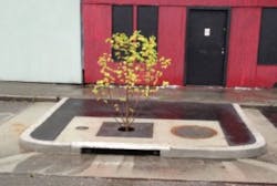
- Seventeen Filterra catch basins– bioretention and filtration units using a tree’s root system with mulch and filter media, contained within a catch basin. Three units were placed at the high-use intersection providing basic treatment and oil treatment (Figure 3).
- Eight StormFilter maintenance holes– a stormwater filtration device utilizing filter cartridges placed within a maintenance hole.
- Two StormFilter catch basins– a stormwater filtration device utilizing filter cartridges placed within a catch basin.
- One BayFilter maintenance hole– a stormwater filtration device utilizing filter cartridges placed within a maintenance hole. This BMP has conditional approval and, at the city’s request, was added as a test case for the city.
- One Perk Filter maintenance hole– a stormwater filtration device utilizing filter cartridges placed within a maintenance hole. This BMP also has conditional approval and, at the city’s request, was added as a test case for the city.
Conclusion
As is the case on many roadway projects when right-of-way space is very limited, achieving the city’s GSI to the MEF requirement of 100% mitigation was not feasible. While GSI is desirable, the current limitation on both the use of porous pavement in the roadway and belowgrade infiltration in the city make it difficult for more than a small percentage of the GSI target to be achieved on an urban roadway. The use of proprietary treatment systems and buried detention pipes is largely a necessity on pavement rehabilitation projects in the city because of space constraints and generally very poor soils for infiltration.
However, it is a step in the right direction for the city to require evaluation of GSI, and, as the process and the technology develop, it will be interesting to see if the mitigated percentages begin to increase to meet the mayor’s goal of managing 70% of the annual rainfall volume using GSI.
The use of three-dimensional modeling software during design proved to be effective in minimizing design changes during construction. Construction is about to enter the third and final phase with no significant redesign efforts needed thus far, despite the complications encountered due to the realities of urban infrastructure.
Although not achieving full GSI mitigation, the project has been a success in meeting the city’s needs, moving smoothly from design to construction, and protecting downstream habitats from the adverse effectsof an urban landscape.
Tye Simpson is the Northwest Area Manager (Seattle); Adam Lee is a water resources engineer (Portland, OR); and Jared Nakamoto is in transportation engineering (Seattle), all with Parsons Brinckerhoff.
About the Author
Tye Simpson, Adam Lee, and Jared Nakamoto
Adam Lee is a water resources engineer (Portland) with Parsons Brinckerhoff.
Jared Nakamoto is in transportation engineering (Seattle) with Parsons Brinckerhoff.


