In early July 2013, 2 inches of rain fell within a 45-minute period at the city-owned Lebanon Municipal Airport in Lebanon, NH. This storm created devastation for the city and the airport, with multiple slope failures and roadway washouts. In all, 3.47 inches of rain fell during the 10-year storm event. A detention pond, perched high on the airport’s hillside, exceeded capacity, causing destruction of the detention pond and outlet swale. With similar incidents having occurred previously, reinforced stabilization measures were needed to prevent future failures.
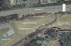
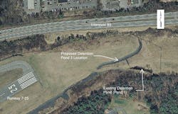
Shortly after the rain event, Hoyle, Tanner & Associates Inc. was hired by the city of Lebanon, on behalf of the airport, to determine the extent of the damage, provide potential solutions and cost estimates, and determine Federal Emergency Management Agency (FEMA) funding eligibility. Hoyle, Tanner’s engineers visited the site to examine the failure areas. The detention pond and outlet swale mitigation at the end of Runway 7-25 later became part of the Storm Damage Project. Figure 1 shows the project area.
Background
In 1992, the Lebanon Municipal Airport received a Federal Aviation Administration (FAA) Airport Improvement Program (AIP) grant to extend the Runway 25 safety area along the hillside adjacent to Interstate 89, creating an approximately 60-foot-high fill slope, at 1V:2H. This runway safety area extension project led to the development of a south side drainage swale that consisted of longitudinal slopes up to 25%. Perforated underdrain pipes were utilized beneath the swale to convey stormwater from the southeast portion of Runway 7-25 toward a cross pipe under Interstate 89 and eventually to the Mascoma River.
An outlet pipe was relocated from the eastern to the western end of the existing detention pond as an 8-inch solid underdrain to convey smaller storm event flows. This detention pond, fueled by a small stream that runs beneath Poverty Lane, is bound by a grassed access road to the north. A stone-lined spillway and a 3-foot-deep, 80-foot-long stone outlet swale were constructed above this underdrain pipe. The outlet swale was intended to act as an overflow weir for the detention pond and was constructed of 18 inches of 6- to 12-inch diameter stone, over 6 inches of 1.5-inch crushed stone and a filter fabric. As part of the improvement effort, the 80-foot-long swale was constructed to convey larger storm event flows along a 50% longitudinal slope and into the adjacent runway safety area ditch line. During larger storm events since construction, minor erosion has occurred within these swales and additional, larger stone had been added.
to the spillway
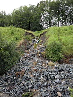
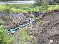
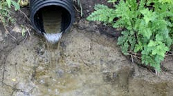
The detention pond failed when the 8-inch outlet pipe beneath the spillway became overwhelmed with stormwater flow from the incoming stream (Figure 2). As the water level rose in the detention pond, the stormwater began to penetrate the spillway berm and flow alongside the underdrain pipe, causing the soils to become saturated and eventually to give way. At the point of failure, a large rush of stormwater flowed through the stone outlet swale with velocities greater than the stones’ capacity and washed it, along with subgrade materials, down the swale (Figure 3). Most of the sediment that was carried downstream collected at the cross pipe under Interstate 89, burring that pipe. Some of the sediment that was washed downstream during this event collected on properties abutting the outlet to the cross pipe under Interstate 89.
Approach
In September 2013, Hoyle, Tanner submitted a conceptual design report to the airport summarizing repair options and associated project costs. The airport distributed the report to FEMA for a grant to restore the detention pond and swales to their original, pre-storm-event conditions. Two options were provided for FEMA’s consideration: an in-kind swale replacement option, and a swale mitigation to prevent future failures. An in-kind replacement consists of restoring the affected area to pre-storm condition, while the mitigation option consists of improving the affected area to prevent erosion damage during similar future storm events. FEMA recognized improvements could be made to prevent future damage and agreed the preferred option was to mitigate the swale to prevent future erosion.
downstream swale
Concurrently, Hoyle, Tanner was under contract with the airport for the Runway 7-25 Obstruction Removal Project that clears approximately 5 acres of trees upstream from the detention pond and outlet swale. This area south of Runway 7-25 consists of two subcatchment areas: one subcatchment area comprises 56 acres and conveys stormwater runoff to the existing Detention Pond 1; the second subcatchment area comprises 31 acres and conveys stormwater runoff to the runway safety area swale. The 5 acres of trees being removed are located within the second subcatchment area, and removing the trees would increase stormwater runoff flow for a 50-year design storm by 6.5%, to 33 cfs. In order to meet environmental regulations including pre- versus post-flows downstream, Hoyle, Tanner proposed reconstruction of the detention pond to capture the stormwater from larger storm events and control its outflow better than it was previously able to do. Additionally, Hoyle, Tanner proposed a new detention pond (Pond 3) in the Runway 7-25 safety area swale, just before the stone-lined outlet swale, to mitigate the additional flows due to the Obstruction Removal Project (Figure 4).
In September 2014, Hoyle, Tanner began the accelerated final design for the Storm Damage Project to accommodate FEMA funding set to expire in December 2014. The design process began with evaluating the concerns and issues of the watershed in conjunction with the subsequent Obstruction Removal Project land development. The accelerated schedule gave the design team four weeks to coordinate the design, prepare and submit applicable permits, and bid with project stakeholders, including the New Hampshire Department of Transportation (NHDOT), New Hampshire Department of Environmental Services (NHDES), FAA, FEMA, the airport, and the city’s Conservation Commission. With knowledge of both the Obstruction Removal and Storm Damage Projects, Hoyle, Tanner recognized the most cost-efficient approach was to combine the two projects, creating a stable slope at the end of Runway 7-25. The airport agreed to the combination of the projects, including the upgrade to Detention Pond 1 and the construction of Pond 3. The combination of the two projects resulted in two funding sources: FEMA for the Storm Damage Project, and FAA for the Obstruction Removal Project. With this combination, quantity match lines needed to be established to break out pay limits for each funding agency.
An Excavation Permit, issued through NHDOT, was required for construction access off Interstate 89. This permit required coordination with NHDOT’s District 2
Office and traffic control plans to demonstrate how access off the interstate would maintain a safe vehicular travel way and a safe work environment for the adjacent construction crews. An amendment to the existing NHDES Alteration of Terrain permit, which had already been approved for the Obstruction Removal Project, was required. An NHDES Standard Dredge and Fill Wetland Permit was also required because of the Obstruction Removal Project wetland impacts.
Previous swale designs and maintenance have included lining the swale with stones to dissipate the velocity within the open channel. Because the July 2013 failure was the second major failure of that stone-lined swale, the City Conservation Commission requested using different material to accommodate the high flow velocities. The commission also preferred to use a more aesthetically appealing product. The proposed design focused on reestablishing the existing swale while accommodating increased runoff from the Obstruction Removal Project. The Northeast Regional Climate Center provides climate and rainfall data for 12 northeastern states, including New Hampshire, and is predicting larger storm events and rainfall depths. These data were incorporated into the design, thus requiring mitigation of higher runoff volumes and flow velocities. The designers proposed a high-performance turf reinforcement matting (HPTRM). These mats are constructed of non-degradable geosynthetic materials that allow vegetation to grow, giving the swales natural appeal and providing channel protection.
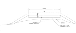
Stormwater ponds in New Hampshire are to be designed to hold a 50-year storm event without overtopping, while meeting predevelopment flows at the project discharge point for two-year, 10-year, and 50-year storm events. While maintaining the existing spillway location for Detention Pond 1, the designers were able to increase the pond capacity by proposing to excavate the opposite end side slopes to 3H:1V. Additionally, the design increased the berm and spillway elevation approximately 3 feet, while maintaining a 10-foot-wide access road along its top (Figure 5). Six inches of humus and 6 inches of crushed gravel were layered on top of low-permeability fill to create a stable maintenance road. The stormwater pond slope treatments proposed 6 inches of humus with a wet basin seed placed along its base and sides to promote vegetation growth in areas anticipated to be inundated with water for extended periods of time.
Design
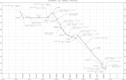
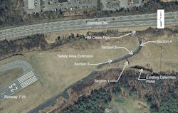
Designers considered multiple solutions to convey flows, including detention pond and swale configurations with treatments including stone lining, check dams, closed drainage systems, and many combinations of each. Based on the steep slopes of the existing swale profile (Figure 6) and past failures, combinations of multiple best management practices (BMPs) were evaluated to convey stormwater to the Interstate 89 cross pipe. With this approach in mind, a two-part closed drainage system consisting of drainage pipes, catch basins, manholes, and detention ponds was selected for the hillside. The closed drainage systems are used to convey the stormwater flow (for storms up to and including a 50-year event) down the steep portions of the swale. The designers utilized the middle portion of the swale for an additional detention pond (Pond 4), to continually slow the stormwater flow and dissipate energy. The proposed design is broken out into four sections, as shown in Figure 7. Section 1 consists of Detention Pond 1 and the 50% longitudinally sloped outlet swale. Section 2 consists of Pond 3 located southwest of the Section 1 outlet swale and safety area swale intersection. Section 3 consists of the safety area drainage swale from Pond 3 to Pond 4. Section 4 consists of the 25% longitudinal drainage slope from Pond 4 to the culvert at Interstate 89. Each section is broken out in more detail below.
Section 1. The outlet to Section 1 is a vertically oriented, 4-foot-diameter concrete outlet control structure designed with two 8-inch orifices to meter the flow of water from Pond 1.
A 24-inch corrugated plastic pipe conveys the stormwater flows from the outlet control structure within a closed system to a manhole, which redirects the stormwater down the 50% slope to a manhole at the bottom. The manhole at the bottom of the slope redirects the stormwater 90 degrees back into the swale via a 36-inch corrugated plastic pipe and end section. Corrugated pipe will be used to dissipate stormwater flow energy, resulting in less erosive velocities at the swale. This proposed swale is designed to accommodate storm events larger than a 50-year event (Figure 8). The proposed swale design includes a keyed stone fill lining, consisting of 6- to 24-inch diameter stones, and geotextile fabric.
At the closed drainage system 90-degree bend, the existing swale also changes direction 90 degrees. This location is where the stone lined outlet swale from Pond 1 meets the adjacent runway safety area ditch line. This is also the location of the proposed Pond 3.
Section 2. Section 2 consists of Pond 3, which adds a berm across the existing safety area swale, creating a collection point for sediments to settle and allowing stormwater flow mitigation through the remainder of the drainage swale. Pond 3 has an outlet control structure similar to that of Pond 1, which coveys smaller storm events to the manhole at the bottom of the 50% slope. An emergency spillway has been designed into the berm of Pond 3 to convey larger storm events to the downstream swale. Pond 3 was designed to store a two-year storm event flow, at a maximum, below the emergency spillway crest.
Section 3. Section 3 is where the closed drainage system from Ponds 1 and 3 outlet. This relatively flat section of the drainage swale runs parallel to the runway safety area. A permanent earth check dam is proposed at the end of this swale, approximately 75 feet from the closed drainage system outlet. This check dam creates a storage area, known as Pond 4, for stormwater flow to accumulate, allowing for continued mitigation of the stormwater flow. Pond 4 is lined with 12 inches of low permeability fill to minimize infiltration into the hillside, and 30 inches of keyed stone fill to help dissipate the flow of stormwater (Figure 9). Pond 4 is designed to detain up to a 50-year storm event while bypassing larger storm events through an emergency spillway designed in the top of the check dam berm. The outlet to Pond 4 is a catch basin located in the pond bottom.
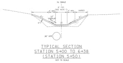
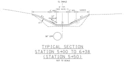
Section 4. The final section of this swale system is Section 4, which consists of the catch basin outlet for Pond 4, in addition to multiple manholes and 36-inch corrugated plastic pipes. It includes the swale that coveys larger storm events, after they spill over the emergency spillway for Pond 4. The closed drainage system is proposed beneath the swale (Figure 10), which consists of approximately 25% longitudinal slopes and outlets approximately 50 feet before the Interstate 89 culvert into a plunge pool. The energy dissipater is a small depression approximately 5 inches deep created by using 12- to 24-inch stone to absorb stormwater flow energy as it leaves the closed drainage system. This portion of the complete drainage swale system is stabilized using HPTRM within the 2-foot-deep swale section and a stabilization fabric on the slopes above the swale. Because of the erosion that occurred from the July 2013 storm event, additional material is required to fill in the existing swale to reach proposed grade. The designers proposed a granular backfill material instead of a regular embankment material to compact better and provide a more solid base for the proposed swale.
and drainage swale
The HPTRM that is proposed for this swale was chosen over a stone fill material to provide a more aesthetically appealing look for this swale, at the request of the City Conservation Commission. The HPTRM was chosen over a traditional turf reinforcement matting due to the steep longitudinal slope of the swale and the potentially large flow velocities that may be present during larger storm events. The design details of how to anchor the matting ends to minimize the seepage of stormwater flow beneath the matting. The matting is anchored with pins or earth percussion anchors. These extend below the fill material and into the undisturbed ground to hold down the granular backfill material and matting above. These anchors include a piece on the end that expands out when forces try to pull the anchor out of the ground.
Ponds 1 and 4 have been designed to detain up to a 50-year storm event, while bypassing larger storms over emergency spillways within the pond berms. With seepage being a factor in the deterioration of the existing pond and swale, the emergency spillways were designed with low-permeability fill material to minimize the seepage through the berm. Additionally, a concrete cutoff wall is proposed within each berm to span the width of the spillway while extending deep enough to be set on existing, undisturbed ground. Anti-seep collars evenly spaced along the drainage pipes will also help minimize stormwater flow seepage along the pipes.
Conclusion
The proposed design included many BMPs to detain and convey stormwater flows within a closed drainage system, appropriately sized open channel geometries, and linings to prevent future erosion. The selected BMPs included enlarging the existing pond (Pond 1) to accommodate the 50- and 100-year storm events, an additional detention pond (Pond 3) to accommodate future runway safety area improvements, installing a permanent check dam (Pond 4) and energy dissipation within an HPTRM-lined swale, installing cutoff walls within the permanent berms, and installing closed drainage systems with energy dissipation on steep sections of the swale. The improvements manage the larger storm event flows, which were originally conveyed by the swale alone, using various BMPs to reduce peak runoff and impacts to downstream properties.
This approach incorporates stormwater practices collectively working to provide a better overall design while integrating land-use changes for future projects. Multiple BMPs and closed drainage systems create effective conveyance of large stormwater flows and high velocities along challenging terrain and steep slopes prone to erosion. The evaluation of swale linings to accommodate runoff included a high-performance turf reinforcement matting, keyed stone fill, and placed stone fill. Performance and aesthetics of the swale linings, as well as constructability, cost control, and providing a long-term sustainable solution were the key components in ensuring project stakeholders make this first response the last response required to stabilize the swale and hillside.
