In the quarter of a century since Subtitle D has been in effect, there have been many great advancements in technologies and materials, but these advancements have not really fundamentally changed our approach to solid waste disposal.
Take the case of bioreactors, which introduced the concept of saturating the waste to promote settlement and leachate and gas production. While evaluation of the bioreactor concept as an alternative technology has proved to be promising, Subtitle D requirements continue to be essentially written around a dry tomb concept that promotes keeping water out.
Vegetated final cover requirements are another area that may deserve another look. Typically these require covering the geomembrane cap with soil to protect the geomembrane from damage and the underlying compacted clay from desiccation. The soil in turn is vegetated to reduce erosion and enhance aesthetics. Final cover has been constructed with a geomembrane, and in many cases an underlying compacted low-permeability soil, throughout the United States. (Soil-only covers are favored in desert climates that have less precipitation.)
The original premise is sound and, for the most part, these final covers have been performing successfully. However, these “traditional” covered geomembranes sometimes come with design and construction issues. Instead of adjusting for soil cover, and designing around it, perhaps it’s time to consider eliminating it.
Soil Cover Issues and Concerns
Slope stability is the chief soil cover issue. Final landfill slopes are often a relatively steep 3:1 (horizontal:vertical) and keeping soil on a plastic surface can be a difficult undertaking. For relatively long landfill slopes (typically 130 feet from bench to bench, assuming 3:1 slopes and 40 feet vertical spacing of benches), a simple infinite slope analysis gives a rather accurate picture of the situation:
In this equation, γ and h with various subscripts denote the density and thickness of various soil layers and depth of water and c is the cohesion between the soil and geosynthetic. Neglecting cohesion (the proper course in the author’s view with the use of secant angle to determine the friction angle) and making the reasonable assumption that the wet density of soil is about twice the density of water (124.8 pounds per cubic foot (pcf) compared to 62.4 for water), the equation can be reduced neatly for two specific cases:
FS = tanØ / tanβ for “dry” slopes
FS = 0.5 x tanØ / tanβ for full saturation
Where:
FS = factor of safety
Ø = interface friction secant angle
β = slope angle
Using textured geomembrane (standard now after 25 years), the post-peak (residual) interface friction angle with most soils can be in the 24- to 30-degree range, which results in a nice factor of safety of 1.3 or more in the dry condition. The suggested minimum depends largely on how one determines the interface friction angle, but a factor of safety of 1.3 is generally acceptable, using post-peak angles. (A friction angle of 29 degrees required for a factor of safety of 1.5 can generally be obtained using peak angles.) These friction angles are secant angles under low loads (< 500 psf) and should not be considered for base liners, where higher loads will result in lower friction angles.
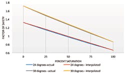
The situation, however, changes dramatically for a fully saturated condition. The factor of safety is less than 0.9 using a high value of 30 degrees, and even less for more typical values for interface friction. A factor of safety less than 1.0 indicates imminent failure, so this is indeed troubling.
Slopes will have some amount of saturation after a rain, but full saturation is unlikely without a long, soaking, significant rainfall. Factors of safety can be interpolated fairly well in between the two extreme cases; for instance, the factor of safety for half saturation, interface friction angle of 26 degrees, and 3:1 slope is 1.1 (0.75 x tan 26/tan 18.6). For this reasonable, and even likely, scenario, even partially saturated conditions lead to a precarious situation. Factors of safety for the full range of saturated conditions for friction angles of 24 and 30 degrees are illustrated below in Figure 1. This graph also shows how well interpolated factors of safety match well with the complete equation.
The concern with saturated soils is typically countered by including a drainage layer over the geomembrane. A gravelly soil can be used to properly drain stormwater and reduce saturation (but not to zero). However, this solution introduces a puncture concern for the geomembrane and may prompt the need for a geotextile filter, adding expense and further complicating the situation.
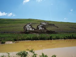
Another option is to use a geocomposite drain. If properly designed, this can reduce the saturation to nearly zero. But now there are more interfaces, which often lowers the interface shear strength. Geocomposite or geotextile interface friction angles can be closer to 20 degrees, which can lower the dry factor of safety in an effort to increase the saturated factor of safety. This underscores the fact that product- and soil-specific interface shear strength testing must be done for proper cover design. Other methods, including soil buttress and reinforced soil can also be used. The bottom line is that proper design and additional cost is required to maintain slope stability. Without proper attention to slope stability, the result can often be slope failure. Figure 2 shows a cover slope stability failure resulting from a combination of low interface strength and erosion.
This erosion is another trouble spot for the traditional final cover. Vegetation is the answer here, but that solution is limited. Stormwater accumulates over long slopes and will erode even vegetated slopes that are much longer than 100 feet. The amount of erosion can be estimated by models, such as the revised universal soil loss equation computer model, downloadable from the Department of Agriculture at www.ars.usda.gov/research.
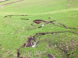
The model takes into account climate (particularly precipitation), soils (some erode more than others), topography (particularly length and steepness of slopes), and land use (predominantly type of vegetation and tilling/maintenance practices). While a value (typically tons of soil per year) can be estimated, the erosion doesn’t occur evenly and rills can typically result from significant storms even for low erosion conditions. Figure 3 illustrates this type of soil cover erosion.
Benches are often used to limit the length of slopes. However, the stormwater that accumulates on benches now has to be transported down the slope in a series of pipes and chutes and the simple solution of vegetating the slope becomes a lot more complicated. In addition, that concentrated stormwater often finds its way out of the collection system and undermines the piping, inlets, and outlets. It then leads to the very thing it was designed to prevent—erosion.
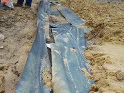
Unforeseen damage can have an adverse impact on the final cover’s actual performance. We know that even the best designed and installed liners have defects, but the very act of placing soil cover may cause additional damage. Figure 4 illustrates an example of damage resulting from cover placement. Settlement-induced stresses, gas pressures, and equipment likely exacerbate the situation further. In addition, differential settlement over relatively flat top decks likely results in lower-lying areas. This can result in ponding of stormwater over the geomembrane and potentially over a defect; adding soil to “fix” the situation makes the ponding even worse. Gas emissions and dead vegetation often happens at geomembrane defects, particularly at well penetrations. New gas rules include provisions for testing gas emission at penetrations. This will undoubtedly lead to the detection of even more emission issues.
There is no question that leachate generation diminishes greatly within the first few years of placing final cover. Even a poor final cover will keep most of the stormwater from entering the waste. The question is not whether or not geomembrane with vegetative covers are performing—by and large they are. The questions is, can it be done better?
Is There a Better Way?
Have you ever asked yourself, “If I knew then what I know now, how would things be different?” I am asking that question today about final covers. We have learned much over 25 years. Whenever a situation occurs, we come up with a “lesson learned,” and we tweak the system some more. We have added to our calculations and specifications, and added a number of components to make the original premise work. What we have not done is taken what we have learned, together with the advances in geosynthetic material science, and challenged the fundamental premise of covering the geomembrane cap.
Suggesting a shifting paradigm may seem a bit pretentious or overreaching—after all, we are just talking about landfills—but I still maintain that the time has come to consider the concept of exposed geomembranes.
Now one might suggest that we would simply exchange one set of complications associated with a covered geomembrane with a new set for exposed geomembrane. To a degree that is correct, because when you remove the soil, you remove the protection that it afforded; specifically protection against:
- Windloads (and gas pressures) that can cause uplift forces that have to be compensated for with some kind of anchorage system.
- Material damage from hail, animals, and vandalism.
- Ultraviolet light that damages the geomembrane over time and reduces its useful life.
Each of these issues have been addressed, and more is being learned each day.
Windloads
Windloads can be estimated, much like stormwater, based on location and likelihood in a given timeframe. Suction pressure is determined as a factor of velocity and location on the slope.
Sp = 0.00124 λ V2 in terms of pounds per square foot (psf) and feet per second (ft/s) accounts for the location on the sideslope and ranges from 0.4 at the base to 1.0 at the crest, with 0.7 generally being used as an average. The design velocity can be obtained from a variety of sources. It is based on location and recurrence interval of the storm with the correct velocity to use left to the designer. For example, a 100 ft/s wind can result in average suction pressure of about 4 psf.
Resistance to windloads can be provided by deadloads, like sandbags or tires, by anchor trenches, or anchors driven through the geomembrane and into the soil. These methods have all been used with success and resisted significant storm events. For instance, the Polk County, Florida EGC, survived multiple hurricanes. Relatively high resisting loads are usually required, however, so sandbags and other dead loads won’t be sufficient except for the most short-term situations. Therefore, anchor trenches or other types of anchors are typically used. As the EGC is a flexible material, the designer must also consider the amount of strain in the geomembrane and as it is pulled upward. While this complicates matters, Giroud worked out an approach years ago (Giroud et al. 1995). While beyond the scope of this article, detailed design procedures do exist.
Material Damage
Material damage has not proven to be as great a factor as originally thought. Without soil, burrowing animals are not a factor, and one can largely prevent vandalism by installing the fencing that is already typically required at landfills. Birds, (and the items they drop) can be somewhat controlled, and accidental damage can be reduced with proper training. Hail and windblown debris would be items outside of the operator’s control, but to the author’s knowledge, such damage has not been significant. While some attempts have been made to compare puncture strengths with the size and speed of projectiles, such a design approach hardly seems worth the effect. The remedy for damage is inspection and repair, which is easily done on an exposed geomembrane.
Degradation From Exposure to UV Light
Degradation through exposure to ultraviolet (UV) light and other environmental factors has been evaluated for decades now. Useful life predictions for some types of exposed geomembranes now exceed 50 years and advances with UV inhibitors continue. Geomembranes are now being manufactured specifically for exposed conditions, and warranties for 30 years are available. Degradation is not the concern today that it was 25 years ago.
Additional concerns would need to be addressed. Although stormwater controls on the landfill are virtually eliminated, more stormwater will be collected and the perimeter conveyance and storage system needs to be sized accordingly. Useful life, although longer than the minimum 30-year post-closure period, is still finite, and what happens after 50 years or so is a discussion worth having. Lastly, an exposed geomembrane cap doesn’t look like a grass-covered knoll so depending on the situation, aesthetics may need to be addressed.
A Less Expensive Approach
This discussion on removing soil cover has thus far specifically omitted cost from the equation. The question has been—is an exposed geomembrane cover (EGC) a better mousetrap, or is it simply a different one with its own set of difficulties? What if, however, it’s a less expensive one?
Here is what you do not have with an EGC:
- Two or more feet of soil that can be a precious commodity on many landfills, and one that gains in value toward the end of a landfill life
- Vegetation and maintaining vegetation along with soil erosion in stormwater channels
- A geocomposite or soil drainage layer
- Benching, along with the associated difficulties of constructing tack-on berms or losing capacity
- Stormwater controls such as downdrains or chutes and associated inlet, outlets, and other features
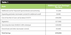
The soil cover, along with all the above necessary “improvements” we have made over the past 25 years, can easily add up to $75,000 per acre, as shown on Table 1.
This cost can be even more depending on the cost of purchasing soil. Onsite soil borrow sources are typically depleted by the time the landfill is fully developed and the $13/CY assumed in this analysis may seem like a bargain. This significant expenditure, from soil to erosion and stormwater controls, adds little to the original goal of keeping water out (and gas in).
An exposed geomembrane can be installed for less than $75,000/acre, which means it’s cheaper to replace (at least once) than to protect. The actual impermeable layer, the primary component of the final cover, costs less than everything put on top. If the geomembrane can function even better without the “toppings”, we have potential for a better and less expensive solution.
The annual cost for inspection and repair is also typically less than the cost for maintaining vegetation and addressing erosion. Annual inspection and a repair of an EGC may take a day or two, and periodic inspections can be done by the landfill gas monitoring staff, or with little additional cost. Soil covers require mowing, some amount of reseeding/sodding, channel cleaning, and perhaps some soil replacement. Annual maintenance savings with an EGC add to the savings in initial capital.
The possibility of an EGC as final cover often boils down to assurance. The local regulators will want some assurance that the EGC can perform as well as the prescriptive soil cover. The owner will want some insurance against replacement cost. The savings from cutting the cost for final cover in half can potentially buy a lot of assurance in the form of insurance. Certainly additional monies can be included in the post-closure fund and extended warranties can be purchased.
Improvements can be made by tweaking a design, but real breakthroughs are made by challenging the original premise and heading in a different direction. That is the opportunity that exists for landfill final covers.
ReferencesGiroud, J. P., T. Pelte, and R. J. Bathurst. 1995, “Uplift of Geomembranes by Wind,” Geosynthetic International, Vol. 2, No. 6. pp. 897–952.
To access additional case studies and in-depth reporting, check out the June edition of MSW Management.
You may need to log-in or subscribe to our magazine.


