View From Above
The industrial site's storm water drainage pattern needed to be mapped with a greater level of detail than ever before.
A client approached TRC, a national engineering, consulting and construction management firm, with a major storm water mapping challenge.
In order to comply with a new industrial storm water permit, storm water drainage patterns across large industrial yards would need to be mapped with a much higher level of detail and accuracy than ever before. In addition to storm water runoff flow patterns, the firm also would need to identify areas of accumulation, determine locations of discharge outfalls and delineate drainage areas contributing to each discharge outfall. Once these features were overlaid onto site plans or aerials showing the locations of various industrial activities at a particular site, potential sources of storm water contamination could be more easily identified and best management practices could be developed. Ultimately, the firm needed to determine whether storm water at any discharge outfall had contacted regulated industrial activities at any point along its flow path.
In addition, the challenge would have to be met more than once. The client had multiple yards affected by new regulations and needed the analysis and deliverables for all the sites completed before strict compliance deadlines.
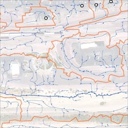
The maps included detailed drainage areas, flow patterns and discharge outfall locations.
Aerial Survey
Traditionally, mapping storm water flow usually has involved placing elevation contour lines on an aerial or base map of the facility and drawing a few arrows by hand pointing in the general downhill direction. This was a narrow and subjective interpretation of flow that would not meet the requirements of the new permit. For the new level of analysis, the team would need to build a high-definition 3-D model of each property, starting with procuring high-resolution elevation data.
The best resolution of readily available elevation data from the U.S. Geological Survey is 10 meters, meaning any feature on the property smaller than that would not be delineated in the data. TRC reached out to traditional airplane-based surveyors it had used in the past. They, however, could only provide resolutions around 5 ft, which was still insufficient for the high-definition 3-D model.
TRC learned of a small unmanned aerial vehicle, or drone, startup in San Francisco called Airphrame, which said it could provide elevations every 5 in. or less using low-cost structure-from-motion photogrammetry. The TRC team found this intriguing, so it thoroughly reviewed a sample of Airphrame's data. They concluded it was the best they could get. Airphrame's costs were a fraction of traditional aerial surveys, and they promised a two-day turnaround after each flight.
Airphrame used custom fixed-wing drones, pre-programmed and autonomously flown about 400 ft above the ground, to capture data from multiple properties per day. Typically it took less than one hour of flight time to survey large yards of 100 acres or more. The company also utilized land surveyors to set ground control points to achieve absolute elevations, along with the relative elevations.
A Model Tool
Having the drones collect the survey data was just the beginning. Next, TRC had to transform the raw 3-D point cloud data—upwards of 100 million data points at each facility—into hydrologically correct digital models. The data contained everything visible during the time of flight, called a Digital Surface Model. However, some features, such as vehicles, tree canopies and stacks of equipment, would need to be removed because they were in temporary locations or not germane to analyzing surface flow. Using LASTools with the BLAST extension pack, the team ran a series of classification algorithms to identify, isolate and remove aboveground features not relevant to storm water flow.
The second part of building a hydrologically correct model is adding in features that may have been beyond the resolution of the drone flight but would certainly affect the storm water flow, like curbs, drains and culverts. Technicians collected GPS data through field surveys on each property, then added these features into the model using the Raster Calculator tool included in the Spatial Analyst extension of ArcGIS.
With a completed custom Digital Elevation Model, TRC could finally begin its flow analysis—but there was no readily available solution that could handle the complexity in the models. Analyzing drainage patterns is a well-established science for large rural areas, where the topography of the ground governs drainage patterns. But that approach would not take into account drains, curbs and other features. Through trial and error and constant revisions, TRC successfully developed a tailored, automated solution for documenting all of these features using more than two dozen hydrology tools from Arc Hydro, Spatial Analyst and other standard geoprocessing tools, but in a customized order with specific parameters every step of the way.
The resulting maps—which included detailed drainage areas, flow patterns and discharge outfall locations—were then utilized by the client’s compliance group to determine appropriate storm water sampling points, and the maps were incorporated into its facility storm water pollution prevention plans.
Further Review
Among the most valuable lessons the team learned about using high-resolution elevation data and GIS-based tools to generate facility drainage areas and flow patterns was that it still needed detailed, on-the-ground mapping of small flow diversion features that can have significant impacts on drainage area delineation and flow.
Thinking ahead, the firm sees multiple ways to take this analysis further. One way would be to develop a method to incorporate multiple layers of flow stacked together, like water below and above a tunnel, bridge or culvert. Another direction would be incorporating ground absorption of water as it crosses various surface materials, which could allow for a more complete hydrogeomorphology analysis. As technology advances, smaller features should be more easily captured, reducing the workload for field staff.


