About the author:
Jessica Donley is marketing manager for CTL Eng. Inc. Donley can be reached at [email protected] or 614.276.8123.
Sometimes the forces of nature—earthquakes, hurricanes and even heavy rains—produce slope failures that cannot be predicted, much less prevented. Many slopes produce warning signs that the earth is about to move. A slope stability analysis requires a comprehensive understanding of the interplay between moisture, soils, structures and gravity. All it takes is good eyesight to detect the warning signs of slope instability, but determining what to do about it is another matter altogether.
It takes experienced, qualified geotechnical engineers to assess the forces at work in a hillside and recommend the optimum course of action to prevent slides, repair existing damage and mitigate future risks. Five common symptoms of slope instability are:
- Visible cracks;
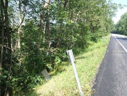
- Leaning or curved trees, guardrails and other structures;
- Toe erosion;
- Hummocky slope surface; and
- Moisture changes.
Many more symptoms will show up in a comprehensive slope stability analysis conducted by experienced geotechnical engineers who have studied these risks in depth. Each slope is subject to the unique characteristics of its gradient, underlying soil and rock, and moisture content. Any roadway or building on the slope adds to the complexity of the stability equation. Furthermore, geographic regions have distinct soil characteristics that make them either prone to slides or resistant to them.
Slope repairs included alternating structural drilled shafts and plug piles.
Diagnosing a Landslide
Near mile marker 13.30 on State Route (SR) 125 in Adams County, Ohio, the unstable ground was causing a landslide. Ohio Department of Transportation (ODOT) District 9 asked CTL Eng. Inc. to test the area, perform design work and complete the final construction drawings in accordance with ODOT standards.
The section of roadway where the landslide occurred was relatively straight and sloped down to the southeast. Frank Young Road—County Road (CR) 56—runs parallel to SR 125 but is located at a lower elevation. The toe of the slope extended down to a creek located approximately 700 to 900 ft southwest of SR 125. The slope instability appeared to be primarily along the southbound/eastbound lane of SR 125, where the existing slope below the road is steeper than 2:1 H:V.
In addition, residents living along the toe of the embankment informed CTL that their houses have experienced lateral movement down towards CR 56. One owner said a tree that was previously further away from the residence had moved laterally towards the house.
CTL initially performed a site reconnaissance to assess the field conditions. During the site reconnaissance, the existing pavement was noted to be in poor condition. Pavement cracks, head scarps and pavement separation were noted near various locations within the project limits. The former guardrail posts southwest of the pavement had been cut off at a grade several feet below the level of the existing pavement, indicating that this area had dropped several feet from its originally constructed elevation. Based on the site reconnaissance, additional tests were recommended by CTL to determine the causes for the landslide and provide slope repair alternatives. The additional testing included test borings, installing inclinometers and taking inclinometer readings, and laboratory testing on soil and rock samples obtained from the test borings.
The drilled shaft plug pile wall's length amounted to approximately 1,500 ft.
Slope Solutions
A total of 10 test borings were drilled at specific locations. In order to minimize the time required for drilling, CTL utilized a three-person drill crew, with the third person primarily responsible for obtaining water for the rock coring operations, preparing grout mixtures and installing flush mount covers for the inclinometers.
Six inclinometers were installed and readings were obtained on a monthly basis for a total of eight readings. Soil samples were obtained from the field, visually described in the field and laboratory, and tested for natural moisture content, grain size analysis and Atterberg limits. Compressive strength tests and triaxial tests also were performed. The recovered rock cores were visually described in the field and laboratory to determine Rock Quality Designation (RQD) and percent core loss values. Representative samples of the recovered rock also were subjected to compressive strength testing.
The subsurface conditions, inclinometer data, stability analysis and site observations indicated that the existing slope was unstable. Evidence of lateral movement was measured at several inclinometer locations. The existing slope appeared to exhibit a rotational type slope failure; therefore, CTL provided two slope repair alternatives: a drilled shaft plug pile wall, and a soldier pile and lagging wall.
ODOT selected a drilled shaft plug pile wall for the slope repair. However, for the chosen alternative, CTL recommended that the roadway be supported with a row of alternating structural drilled shafts and plug piles installed off the edge of the roadway. The structural shafts were reinforced with steel sections and then filled to their full length with structural concrete. The structural shafts were socketed into sound rock. The total length of the drilled shaft plug pile wall was approximately 1,500 ft.
It is crucial to assess all the potential points of failure on a slope with experts. Anything less leaves too much to chance.


