Building Usable Sites, One Block at a Time
Besides shoring up existing land, retaining walls also can allow for the expansion of buildable area on a site. Throughout the nation, many sites previously thought unusable have been developed as builders use retaining walls to soften steep slopes with terracing or create a flat, stable parcel of land in hilly areas.
Creating Space
When the Poway Unified School District, located in a suburb of San Diego, CA, needed to construct Westview High School, two small, wooded canyons were the only space available for such a project. The problem: how to turn undeveloped and seemingly unusable land into a large school campus.
Grading contractor Sierra Pacific West Inc. began by removing trees, cutting away, filling, and grading the two canyons until only a buildable site existed. The most extensive soil cuts were approximately 60 to 70 feet deep; the fill area was 40 to 50 feet high. A geogrid-reinforced retaining wall was built on the site using a combination of blocks from Keystone Retaining Wall Systems to deal with substantial grade and soil-retention issues. RCP Block & Brick of San Diego, which has been producing Keystone products since 1992, supplied the almost 20,000 square feet of Keystone’s Standard, Compac, and Planter units used in the retaining wall. Before a single block was placed in the project, however, excavation challenges at the site had to be met.
Sierra Pacific West Vice President Chad Sheridan recalls the situation: “Why build a high school there? The site had been chosen, and had been under development, for almost 10 years. At one time even the Army Corps of Engineers had been involved. There was a canyon on each side of the site, with hills that reached about 70 feet. We first cleared all trees, including a eucalyptus grove. We needed to level the hills into the canyon to make a flat area for construction.”
Leveling the land didn’t always go smoothly, however. “We discovered concretions—silty-sand soil compressed until it was the consistency of concrete,” Sheridan says. “The excavators couldn’t break those concretions—not even the large D-9 dozers. We hit 1 to 3 inches of cobbled ‘cement’; some chunks were as large as pickup trucks! However, even if we’d known about the concretions before we made our job estimate, it still wasn’t something we couldn’t deal with. In effect, it allowed us to create onsite backfill. We crushed the concretions in a 10,000-pound breaking machine, which was a little more costly than the cost of offsite fill, but then we didn’t have the expense of trucking fill for those voids. In one way, it was nice, because we could break the concretions to the precise size we wanted—pieces that could be handled by a 980 loader for placement into a crusher. We stockpiled the material there, and Geogrid Retaining Wall Systems actually backfilled the walls.”
After the appropriate excavation was complete, the school site was 30 feet above the area designated as the athletic field. “Because every acre of buildable land was needed to complete the campus, it was impossible to consider a slope for this site,” says Mike Stevenson of Geogrid Retaining Wall Systems Inc. “A 2-to-1 slope with a 30-foot rise in elevation would mean the loss of 60 feet back and across the line where elevation began. Every inch of that valuable space was needed to build the athletic field.” The solution: a near-vertical segmental retaining wall.
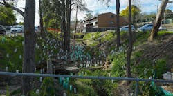
As the wall was installed, other challenges called for creative measures, such as the deep footings required for the large light posts. Sonotubes were used to build the footings in the fill area, and soil was compacted around the tubes as the crew added fill. A 6-foot masonry fence parapet was to be built on top of the segmental retaining wall; construction design had to be coordinated so the fence’s footing was atop the topmost retaining wall block and cantilevered back into the fill. The installation crew had to ensure that the geogrid was low enough to accommodate the footings.
The wall also features a distinctive blue “W” design, which was built using contrasting blue Keystone units. “The ‘W’ in the wall was a last-minute thing,” Stevenson concludes. “The idea came up late into the design. They asked me for my opinion on how it could be accomplished, so I took a set of plans and colored in the appropriate blocks.” RCP Block & Brick tinted a number of Keystone blocks for the purpose.
Saving Valuable Land
While retaining walls can help create more land, they also protect nearby lands. When the Maryland Transportation Authority reconstructed the Interstate 95/JFK Memorial Highway interchange at state Route 22 in Harford County near Aberdeen, it needed not only to improve traffic flow but also to protect natural water flows in the area.
The $23 million project included the construction of diamond loop ramps, collector-distributor roads, and bridge replacements and dualization of Maryland Route 22. Traffic at the interchange is expected to skyrocket in coming years, as it’s adjacent to the new Cal Ripken Stadium, home of the Aberdeen Ironbirds a Baltimore Orioles farm team of baseball’s Class-A New YorkñPenn League. The stadium complex, completed in 2002, is the first phase of a multimillion-dollar “Aberdeen Project” planned to encompass 112 acres of land development off I-95.
Jeff Basford, a geotechnical engineer with Whitman, Requardt and Associates LLP, the project design consultant, explains some of the project’s challenges: “The overpass over I-95 was the main portion of the project. It was old, and it needed to be wider. In addition, since I-95 was being widened, the overpass bridge also needed to be longer.“The site originally contained a 2:1 slope,” he notes. “The design was constrained by wetlands. That’s why a wall was built, as opposed to a slope.” The maximum height of the wall was 23 feet; it has a vertical face with 2H:1V toe slope at the bottom of the wall.
As the water table was a foot or so below the bottom of the wall, springs were popping up and water was seeping through the back of the wall. Some underdrains also outletted in the slope. Wall widths are typically 0.7 times their height. However, because of the soft soil an organic, high-plasticity clay and the adjacent wetlands, geogrid straps were placed 30 feet behind the face of the wall.”
Geogrids and Mesa segmental concrete blocks, both from Tensar Earth Technologies, were used in the construction. Together, they create a positive, mechanical, end-bearing connection, with a compressive strength that exceeds American Association of State Highway and Transportation Officials (AASHTO) standards of greater than 4,000 pounds per square inch.
To handle the water, we used number-57 stone a free-draining, approximately 0.75-inch crushed stone for drainage,” Basford notes. The wall includes 24-inch-diameter drainage pipe penetrations. “Also, the site presented problems with slide and bearing capacity, so we ended up with a small berm in front of the wall.”
The project began with the general contractor, Daisy Construction Company of New Castle, DE, cutting out the area. “They went about half way(15 feet of slope were removed,” Basford says. Stone and grids were placed, but because of the location of the access roads, dump trucks were driving over the geogrid. “The owner decided to undercut the second half of the wall—the north half—and stabilize it. The wall had to be built in smaller sections, so they could then put the wall in the way they wanted. Perhaps the biggest challenge was the wall’s bottom 3 feet until they made the decision to undercut it. They weren’t used to the soil they encountered, so the grids kept getting messed up. After they got out of the ground, the next challenge was laying out the grids and having to stress how taut the geogrids had to be. In filling the wall everyone had to make sure the wall itself was meshed up to the existing ground.”
Because the interchange needed to be lit, light pole foundations were anchored 15 feet deep within the reinforced zone. “Corregated metal pipes were installed at the bottom, and as they went up they placed the collar and put geogrid around it. The pipes were used as forms for the light pole caisson foundation,” Basford explains. “The MESA wall installer, Mumford & Miller of Odessa, Delaware, liked the system’s ease of installation, and the company is now working on other Mesa wall installations.”
Saving Valuable Streets, Bridges
For 20 years, an H-pile and wood lagging retaining wall had secured the Lawndale Drainage Channel in Tupelo, MS, but time had taken its toll. The wood had rotted and could at any time allow a major washout and the wall was immediately upstream from a bridge on Lawndale Drive, a major Tupelo street.
The channel, which is 20 feet wide by 10 feet deep, carries a considerable amount of water during storms,” says James Glasgow of Con-Terra Construction of Fulton, MS, the company that replaced the wall. “The channel doesn’t crest over its banks, but water lapped at an adjacent residential property. The owner wanted something done.”
Working with Tupelo’s Rutledge Construction, the managing contractor, and engineers from Neel-Schaffer Inc., Con-Terra suggested the best and fastest solution would be a segmental retaining wall. “They’re ideal for a drainage channel; they don’t have mortar to deteriorate. Of course, that’s if you can get them in before flooding,” Glasgow says, noting that, because the hurricane season was fast approaching, time was of the essence. In February 2003, Rutledge Construction removed the debris from the failed wall, and Con-Terra began work on the replacement wall.
First, the channel water was diverted by building a coffer dam to direct flow to the other side of the channel,” Glasgow explains. “We put down a foundation of crushed stone compacted to 95%, then put in the first course of block, which always takes the longest time. Although the area has silty loam soil, which had to be replaced by importing a lot of sand, the lower depths were filled with hard chalk soil, so we proceeded with three courses of geogrid.” Con-Terra used the StoneWall Select system from ICD Corporation of Milwaukee, WI, for the project. “These walls are unusually strong, easy to build, and among the most attractive on the market.” Glasgow says.
The wall plans, designed by Little Rock, AR, engineer Scott Miller, called for a segmental retaining wall 112 feet long and 10 feet tall, with over 1,700 square feet of surface area. Six geogrid layers were needed to stabilize the bank and provide rigidity. “The geogrid has to be stretched back 8 feet behind the wall, and anchored by putting dirt over it,” Glasgow notes. “You have to come up and pin the geogrid at the block line with stakes. We placed 2 feet of block in between each geogrid—in total, about 1,000 square yards of geogrid.”
Designed to look like natural stone, StoneWall Select offers a patented clip-positioning system that snaps multiple courses of blocks together. The blocks have hollow cores that are filled with crushed rock, which adds strength and positive connection between courses of blocks.
Con-Terra’s construction crew of six finished the project in seven working days with the aid of some unusual equipment. “We normally use an excavator and trench compactor,” Glasgow says, “but in this case, we had to use a trackhoe forklift—a Skytrack forklift with extend-a-boom—with a bucket, so we could reach across the channel.” The wall was completed in May 2003, before summer thunderstorms and the impending hurricane season.
This no-maintenance wall will last just about forever, and it looks nice—much more attractive than the previous wall,” Glasgow concludes. “It also ended up being a more cost-effective solution. It was about 25% cheaper than a concrete wall, and up to 50% less money than a treated-wood and H-pile wall.”

