Stormwater runoff, consisting of moving water both during and in the aftermath of a downpour, may be managed (or mismanaged) in a number of ways. As described in the Alabama Handbook for Erosion Control, Sediment Control and Stormwater Management, “In an undeveloped area, stormwater runoff is managed by nature through the hydrologic cycle. The cycle begins with rainfall. Rain either stands where it falls and evaporates or it is absorbed into the ground near the surface, to feed trees and vegetation, ultimately to be returned to the atmosphere by transpiration; or it percolates deeply into the ground replenishing the groundwater supply. The remainder of the rainfall collects into rivulets. This collected runoff increases in quantity as it moves down the watershed, through drainageways, streams, reservoirs and to its ultimate destination, the river and then the sea.”
But, the document continues, “This simple explanation of the hydrologic cycle belies its complexity. Nature’s inability to accommodate severe rainfalls without significant damage, even in undeveloped areas, is very apparent. Nature’s stormwater management systems are not static but are constantly changing. Streams meander, banks erode, vegetation changes with the seasons, lakes fill in with sediment and eventually disappear.”
Of course, in developed areas, additional problems may present themselves. Some of the potential hazards, according to the Alabama handbook, include:
- An increase in developed areas exposed to stormwater runoff and soil erosion
- Increased volumes of storm runoff, accelerated soil erosion and sediment yield, and higher peak flows caused by:
a) Removal of existing vegetative cover
b) Exposure of underlying soil or geologic formations potentially more erodible than the original soil surface
c) Reduced capacity of exposed soils to absorb rainfall due to compaction caused by heavy equipment
d) Enlarged drainage areas caused by grading operations, diversions, and street construction
e) Prolonged exposure of unprotected disturbed areas due to scheduling problems or delayed construction
f) Shortened times of concentration of surface runoff caused by altering slope steepness, slope length, and surface roughness and through installation of “improved” storm drainage facilities
g) Increased impervious surfaces associated with the construction of streets, buildings, sidewalks, and paved driveways and parking lots - Exposure of subsurface materials that are rocky, acidic, droughty, or otherwise unfavorable to the establishment of vegetation
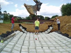
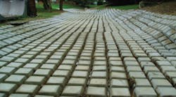
CC 45 Cable Concrete articulated concrete block mattress allows infiltration between the blocks and can be overseeded if desired.
Along with these problems come the various associated oil, grease, metals, pesticides, fertilizers, and other waste products that are washed off with storm events, adding to the pollutant load entering drainage channels.
Thus, as stated in the North Carolina Erosion and Sedimentation Pollution Control Program, “Upstream development accelerates channel erosion by increasing the velocity, frequency, and duration of flow. As a result, many natural channels that were stable become unstable following urbanization.”
But solutions abound. In stormwater pathways natural or manmade, a variety of soft armor and hard armor resources are available to repair deteriorating drainage channels.
When channel flow velocities are slow enough to warrant it, natural vegetation of the channel bed is often the ideal method of preventing soil from washing away. According to the North Carolina publication noted above, “Dense, vigorous vegetation protects the soil surface from raindrop impact, a major force in dislodging soil particles and moving them downslope. It also shields the soil surface from the scouring effect of overland flow and decreases the erosive capacity of the flowing water by reducing its velocity. Suitable vegetative cover affords excellent erosion protection and sedimentation control and is essential to the design and stabilization of many structural erosion control devices. Vegetative cover is relatively inexpensive to achieve and tends to be self-healing.”
Another benefit of channel vegetation is the enhanced infiltration of the water runoff into the soil, filtering out both pollutants and sediment from the flow.
For higher flows, vegetation may be combined with geosynthetic fabrics, such as turf reinforcement mats, in
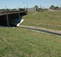
The Antelope Creek project looks natural, yet has the ability to withstand the events that occur there.
which vegetation grows through the fibers. Such mats serve to add additional support to the existing vegetation.
However, when flow velocities exceed the capacity for vegetation-based solutions, various forms of hard armor may be called for to protect the channel bed and to provide bank stabilization. Some of these methods include poured concrete, articulated concrete blocks, riprap, gabions, and cellular confinement systems.
Poured concrete can minimize channel and bank instability but has a number of drawbacks. There is no infiltration into the soil, so any pollutants in the runoff are simply carried downstream, instead of being removed from the flow. In addition, flow volume and velocity increase, creating greater problems at the point where the concrete lining ends.
Riprap, essentially broken chunks of concrete or stone, is another solution to channel and bank stabilization, but many communities view this as a measure of last resort due to the often unattractive appearance it offers. In addition, the riprap components may dislodge with heavy water flows, reducing or negating their effectiveness.
The other hard armor options noted above will be discussed in the case studies that follow.
Opa-locka Canal Project
Located in Miami-Dade County, FL, the city of Opa-locka has experienced significant flooding throughout much of its 4.2 square miles for many years. Erosion and sediment control firm R. H. Moore & Associates explains the problem: “This is due, in part, to the geographic location of the city, which was developed on a flood plain. Several factors have contributed to the flooding of the city’s low-lying areas, including a limited plan of action to manage surface water runoff conditions and no regularly scheduled canal cleanup plan to prevent obstructions that impede flow. The canal system that surrounds the entire city had been experiencing severe erosion resulting in sediment laden canals, which reduced the volume for stormwater runoff, as well as harming the water quality. It was clearly determined by city managers that the canals would have to be dredged and the side slopes protected from future erosion.”
Larry Larson Jr. of R. H. Moore & Associates describes a problem common to Florida’s coastal communities. “Florida canal embankments are being eroded during storm events with undermining occurring at the waterline [that is] caused by wind and boat-generated wave chop,” he says. “When undermining occurs at the toe, the slopes begin to slough off into the water. Slopes steeper than 2H:1V normally start sliding under saturated conditions until the soil reaches a point of equilibrium. Florida is especially susceptible to this type of erosion due to our sandy soils.”
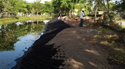
The city of Opa-locka has experienced significant flooding throughout much of its 4.2 square miles for many years.
Larson explains that in 2002, a hurricane that struck south Florida wiped out most of the Opa-locka Canal at the water line, resulting in steep 2-foot dropoffs in places. This presented a serious danger to the many children who enjoy fishing along the canal’s banks. Because the sand in this part of Florida is very fine, it “turns into soup and washes away,” Larson says. Layers of soil keep falling into the canal, causing these hazardous dropoffs. Worse still, tall weeds began sprouting, presenting ideal hiding places for the area’s alligators.
Because of the city’s proximity to the Atlantic Ocean, the Opa-locka Canal experiences wave chops, for which a 4:1 (horizontal to vertical) bank slope is generally required. In addition, the water level within the canal fluctuates quite a bit-lower in the winter and higher in the summer.
A decision had to be made regarding which of many solutions to incorporate into the stabilization of the canal. Larson explains some of the factors considered. “We looked at many types of products for this canal, from soft-armor bioengineering solutions to hard armor such as articulating block and gabions. The Geoweb system [manufactured by Presto Products Company] was chosen based on the velocities of the canal and the overall look that the city was trying to achieve. They were trying to give these canals a sort of linear park along both sides. The city was looking for a place that the residents of the area could use as a park and where they could have access to the water without the fear of hidden alligators. The Geoweb system solved that problem.”
The Geoweb cellular confinement system is designed for either intermittent or continuous levels of low-to-high water flow, according to Bill Handlos, P.E., CPESC, of Presto’s Geosystems group. “The Geoweb system acts like a flexible form,” he explains, “confining a variety of infill materials in typical applications such as swales and drainage ditches, stormwater diversion or containment channels, process water channels, culvert outfalls, and spillways.”
Larson found that the various options for infill material were particularly useful for this project. “Geoweb offers a unique option for erosion protection for canal side slopes; you can fill the cells with rock or concrete to about one foot above the mean high water line. The choice between rock and concrete is based on the velocities and wave attack encountered. Above the mean high water line, you can fill the cells with soil and sod or seed directly over the filled cells. A rock infill below and sod above was chosen for the Opa-locka project.”
More than 5 miles of the Opa-locka canal system was restored in this manner, although severe storms pose a constant threat. “The canal was designed to meet certain criteria based around a 25-year storm event,” Larson says, “but designing to meet hurricane-force conditions is almost impossible. This area may never be hit again by the type of storm that did all the damage, but, on the other hand, we may get hit four times in one year like we did back in 2004.”
Frost Hollow Swale
The Frost Hollow swale is a channel running through a residential development in Forks Township, in Easton, PA. Historically, during heavy storms, this channel has been unable to move the stormwater runoff quickly enough, causing localized flooding that entered the basements of nearby homeowners. In addition, the channel banks were eroding away, and Frost Hollow had formed several 90-degree turns. Deep erosion was occurring, and nearby properties were eroding as well.
Then, in 2005, the area suffered two or three “100-year floods” according to David Faust of Bethlehem Precast Inc. He notes that the current concept of a 100-year flood may be somewhat antiquated. “Since there is so much building and construction going on,” he says, “we’ve got a concrete jungle and a rising water table, especially in highly populated areas.”
As an aside, a number of engineers appear to agree with Faust’s assessment. The Alabama Handbook for Erosion Control, Sediment Control and Stormwater Management comments, “Studies have shown that most natural stream channels are formed with a bank-full capacity to pass runoff from a storm with a 1.5 to 2-year recurrence interval. As upstream development occurs, the volume and velocity of flow from these relatively frequent storms increase. Even smaller storms with less than 1-year recurrence intervals begin to cause streams to flow full or flood. Stream channels are often subject to a 3- to 5-fold increase in the frequency of bank-full flows in a typical urbanizing watershed. This increase in the flooding frequency places a stress on the channel to adjust its shape and alignment to accommodate the increased flow.
“Unfortunately, this adjustment takes place in a very short time period (in geologic terms) and, the transition is usually not a smooth one. Meandering stream channels which were once parabolic in shape and covered with vegetation typically become straight, wide rectangular channels with barren vertical banks. This process of channel erosion often causes significant property damage, and the resulting sediment which is generated is transported downstream, further contributing to channel degradation.”
This was the process occurring with the Frost Hollow swale. “There is a huge development upstream,” notes Faust. “There is water feeding in from area roads; there is the stormwater runoff. There are some runoff basins for water retention, but these are not sufficient for major storms.”
To solve the problem, the Frost Hollow channel was widened. Initially, soft protection was used, in which a screening mesh was applied and overseeded with grass. However, these measures were put in too late and the grass couldn’t get established before the next heavy storm event. It washed out, and then the decision was made to replace the screening mesh with CC 45 Cable Concrete articulated concrete block mattress manufactured by International Erosion Control Systems. Design engineer Ryan Christman of Keystone Consulting Engineers was free to select what he thought was best for the project-there were no specific municipal requirements. But Faust notes that the Pennsylvania Department of Environmental Protection has approved Cable Concrete as an acceptable best management practice for stormwater management and adds that the CC 45 is highly effective in dealing with the high water velocity and the regular strong storm events in the area.
Cable Concrete consists of pyramidal-shaped concrete blocks interwoven with stainless steel cable and underlaid with an erosion-minimizing geotextile fabric. It allows infiltration between the blocks and can be overseeded if desired.
Faust explains that the purpose of the Frost Hollow channel is both to move stormwater runoff and to allow infiltration into the ground. “The benefit of the articulated blocks is that grass grows over and between the blocks, causing a filtering benefit as well as a better aesthetic appearance,” he says. “Within a relatively short period of time the area looks very natural. In this specific project, we did not overseed with grass but let nature take its course. Over time, the area silts up and vegetates naturally. Now, a year and a half after the project’s completion, it looks quite natural, and before long, you won’t be able to see the articulated blocks at all. This vegetation, of course, slows down the velocity of stormwater, and you get infiltration, which is what you want.”
The Frost Hollow project was completed in September 2007, and Faust notes that engineers involved with the effort are quite pleased. A total of 362 eight- by 16-foot Cable Concrete mats were used, along with 181 four- by 16-foot mats, totaling nearly 58,000 square feet. The channel has been successfully widened, erosion appears to have been arrested, and the channel treatments have performed exactly as desired. There have been several major storm events since the installation, with no reports of any new basement flooding.
Antelope Creek
Antelope Creek is a small stream running through Lincoln, NE. As noted in the Antelope Valley Study issued by the city of Lincoln, the creek meanders in an open channel underneath a number of street bridges and through many residential and business neighborhoods until it moves underground into an enclosed conduit. From there, it travels underneath several buildings, re-emerging aboveground a couple of blocks later. The final leg of the creek again meanders in an open channel underneath more street bridges, passes through the campus of the University of Nebraska, travels underneath railroad tracks, and finally empties into Salt Creek.
“Because of increased runoff caused by urban development in the lower reaches of the Antelope Creek basin,” states the Antelope Valley Study, “only a four-year or smaller storm is calculated by the engineers to fit into the conduit, and any larger storm would exceed the conduit and cause the excess water to travel overland, flooding many … neighborhood streets and properties.”
Furthermore, a number of street bridges over the creek are so small and low that as the creek rises, these bridges act as small dams, contributing to the flooding of nearby properties. The study estimates that in a 100-year flood event, some areas would be under up to 6 feet of floodwater. In an analysis by the US Army Corps of Engineers, it was determined that even an 8-year flood would result in widespread damage.
Over the past century, Antelope Creek has flooded numerous times, most severely in 1908, when 10 lives were lost.
The goal of the Antelope Creek flood control project is to reduce the estimated annual flood damage by 80%, as well as to confine the 100-year storm event within the channel banks.
Wayne Wendel of Contech Construction Products in Lincoln notes that erosion concerns existed as well, but because of increased surface runoff caused by the impervious surfaces from city development, continual flooding was the primary issue with Antelope Creek.
Wendel explains that the Joint Antelope Valley Authority (JAVA) “pushed for a “˜green’ solution,” desiring “a channel that would look natural, yet have the ability to withstand the events that occur here.”
JAVA has produced a 20-year development plan for the creek basin, incorporating work on three channel reaches. “I have been involved with all of them from the very beginning,” Wendel says. “Presentations on ArmorFlex”-an articulated concrete block revetment system-“and erosion control TRMs [turf reinforcement mats] were given to JAVA prior to the design being completed. We then worked with the corps and the engineer [Olsson Associates of Lincoln] to size the ArmorFlex and TRMs. The project is ongoing. Hawkins Construction Company of Omaha has been the contractor that has performed the work up until the most recent bid, which was just awarded to Park Construction out of Minnesota. We have approximately 100,000 square feet of ArmorFlex to supply for the phase that just bid.”
Continuing downtown development increases the problems faced from channel flooding. “Antelope Creek is the main drainage channel of the city, and with the development of recent years, it had become undersized,” stresses Wendel.
He explains that curative options were somewhat limited. “There was no soft armor available-and still isn’t-that can withstand the shear forces and velocities present in the channel. I would estimate that any hard-armor solution is going to cost approximately 2.5 to 4 times what a soft-armor solution would, the caveat being that most times ArmorFlex is being considered as a design solution, there simply is no soft-armor solution.”
The Antelope Creek flood control project is still ongoing, but Wendel says that the creek has been treated to allow silt to settle out, and the ArmorFlex used is designed to allow the establishment of vegetation, producing some level of water treatment. However, “the main goal was to move water.”
To date, Wendel says, “The reaction has been very positive from the business owners and public officials. There was some resistance to the project from some homeowners and business owners that had to give up property. However, that stemmed from the road and bridge projects that went along with the channel improvements. It was the new road and bridges that caused most of the negative reaction because of the eminent domain issues and establishment of easements. Like many things, the public doesn’t like the delays and inconvenience during construction, but will be very pleased upon completion, and are already pleased with the performance of the channel.”
Neabsco Creek Channel
Neabsco Creek is a tributary of the lower tidal segment of the Potomac River located in eastern Prince William County, VA. Alan Dinges, assistant area manager for Maccaferri Inc., says, “The creek has served as a vital waterway for trade and commerce in northern Virginia since the eighteenth century. The EPA Office of Water has identified the Neabsco Creek watershed as an “˜area of significant habitat degradation’ due to a loss of natural land cover and stormwater management facilities designed without consideration for environmental conditions.”
Because of its sandy soil and a steep slope, a hillside drainage channel emptying into Neabsco Creek was suffering severe erosion. The county hired engineering firm R. A. Smith National Inc. and specified that gabions (essentially rock-filled baskets) should be used to stabilize the drainage channel. This firm contracted with Maccaferri in Williamsport, MD, for design work.
According to Maccaferri’s Larry Bakner, “Maccaferri provided an initial design for consideration. The project went through numerous revisions, and a final design was decided on in the spring of 2008. Upstream development was the reason for concern on this project. A large commercial development, 650,000 square feet, was to have three outfall areas with 48-inch and 54-inch concrete pipes. The design flows were 120 and 160 cubic feet per second for a 100-year event, with velocities around 10 feet per second.”
Bakner explains the primary goal of the work: “The channel was designed to move the water from the commercial site into an existing stream, and also to dissipate velocities. An inspector was continually onsite during construction to monitor the water quality in the stream.”
Dinges adds, “This project has very high visibility, and this is the reason it was monitored so closely.”
As with the Antelope Creek project, options were limited, especially because the county had specified the use of gabions to repair the channel. “A soft-armor solution was not considered,” Bakner says. “Gabions and riprap were both considered as solutions, but due to the steep slope and water velocities, gabions were chosen as the best solution.”
The gabion installation was completed shortly after the final design approval. It consists of approximately 1,400 cubic yards of galvanized gabions, placed on top of Maccaferri’s MacTex MX-275 nonwoven geotextile material. The resulting gabion structure is quite striking and appealing to the eye, in stark contrast to the initial appearance of the eroded channel. Bakner notes that, not surprisingly, the engineers were quite pleased with the results.


