Hurricane Sandy hammered the northeastern US in late October 2012. By the time Sandy reached Long Island, NY, it had been downgraded to “only” a superstorm. Nevertheless, it has been estimated that the resultant tidal surges, high winds, and heavy rains condensed what would have been roughly 30 years of expected erosion into three days of actual, devastating erosive effects.
Located approximately 35 miles from New York City, West Shore Road is a vital commuter link between the communities of Bayville and Oyster Bay on the North Shore of Long Island. The roadway runs along the edge of Oyster Bay Harbor and had been supported by a boulder seawall constructed more than 50 years ago. This seawall, which had been repaired and patched numerous times, was torn apart by the massive storm. As a result, West Shore Road was almost completely destroyed.
Adam Baker of LHV Precast notes that even prior to the storm, Nassau County had been working to upgrade the road. “They had the foresight to understand that the West Shore Road and seawall needed to be replaced, and, therefore, a new road design was commissioned and a contractor was scheduled. The only challenge that remained was how to fund the project. An estimate of $9 million had been projected for the first phase of the project but had been difficult to procure before the storm. Fortunately, after the disaster, the funds became available through FEMA, which stepped in with the necessary funding to help in the recovery efforts.”
Originally, the engineering firm responsible for the road design envisioned a poured-in-place wall. “But they were concerned,” Baker says, “that this methodology required a large cantilevered footing and long forming and curing times before backfilling, as well as leaving open excavations for extended periods of time.
“That is one of the advantages of the Stone Strong retaining wall system that was ultimately selected. We ended up going with the 24 SF 86-inch extended block, and some 24 SF 6-inch mass extenders to be able to control the forces of the road above and the tides in Oyster Harbor.”
By March 2013, LHV Precast began delivering Stone Strong retaining wall blocks to the site, and construction was completed in time for local Fourth of July celebrations. Just over 27,000 square feet of retaining wall-a distance of more than 2,250 linear feet-was installed. The height of the wall ranges from 12 feet to a little over 16 feet tall.
“The biggest challenge was building a gravity wall at that height,” says Baker. “It required the Stone Strong 86-inch extended block. We were able to take advantage of that block’s additional length to change the center of gravity of the wall, so we could build higher.”
He also mentions that on this project, the wall needed to be buried much deeper than normal.
“Typically, we require only 9 inches of bury with the Stone Strong retaining wall system, but once we break a 9-foot height, I hold the rule, as do most of the engineers we work with, that for every one foot of vertical, we want an additional one inch of bury. So if the wall is 12 feet tall, you’ve got to bury it 12 inches. But because they were concerned about the sand and the beach erosion, since there was wave motion with low and high tide, we made sure we had 60 inches of bury. We were holding the road in, and they were concerned about possible additional erosion in the future.”
Another potential concern, at least prior to the storm, is that a wildlife sanctuary sits very close to the edge of the previous retaining wall that had been in place. The engineer had to obtain permits to be able to encroach upon the area. “But once it became a Hurricane Sandy disaster, those restrictions were loosened up greatly,” Baker explains.
He also notes that because sufficient space was available, a 6-degree batter could be used, which was uniform across the length of the wall.
To assist drainage, infill of three-quarter-inch stone was placed inside the Stone Strong retaining wall blocks. “Because we were underneath the road, the backfill was a select structural fill, 4-inch-minus, evenly graded, compacted to 95%,” says Baker.
He points out the importance of keeping excess water away from the building site. “One of the challenges that they had was dewatering while they were doing the construction. They built a sheet pile cofferdam that they would hopscotch forward as they progressed. Then, on top of that, they had installed a large metal container that they used to pump the water into so they could control the water between the cofferdam and the road as they were constructing the retaining wall. I thought the ingenuity behind that was quite amazing on the part of the contractor. I was very impressed by that.
“To keep their construction schedule moving forward and flowing, they did something like 200 feet of cofferdam, and they would build about 150 feet of wall. They would then stake the 50 feet from the other end and move the cofferdam forward, constantly hopscotching. Then they just used sandbags between the new retaining wall at the one end and the existing seawall that was left at the other end, to block it off at each end.”
Retaining Walls at Port Canaveral
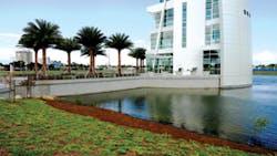
A beautiful and unusual seven-story welcome center has been built at Port Canaveral near Cocoa Beach andCape Canaveral on the east coast of central Florida. The area is home to cruise lines and cargo shippers taking advantage of the first-class deep-water port and is visited by tourists enjoying the beautiful beaches. The welcome center, in a parklike setting, has been variously described as having the appearance of a rocket ready to launch, a surfboard standing upright in the sand, or a ship’s hull.
“It is quite an impressive building, and there are surrounding ponds as well,” says Randy Hart of RWH Construction Services Co. His firm constructed multiple retaining walls at the site.
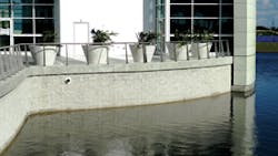
“There were four separate walls on the project-one on each side of the roadway that they refer to as a bridge, and one on each side of the building,” he explains.
“We were first approached by the contractor about doing a retaining wall for this project. I think originally the job was designed with a cast-in-place concrete retaining wall, but they wanted to look at doing it with a segmental block retaining wall. The cast-in-place system might have been cost prohibitive. Also with this project, the building was built before the retaining walls went in at the bottom of the building, so there would have been a problem with excavating and shoring up a cast-in-place wall.
“We felt the project had some complexity to it. We wanted to provide a retaining wall system that would be pre-engineered by the manufacturer. So for this, we used Tensar’s Mesa system. They engineered the wall and provided the materials, and we installed the wall and did concrete topping for the wall.”
Hart explains that approximately 22,000 square feet of retaining wall went into this start-from-scratch project. No previous retaining walls had been in place.
Tensar HDPE uniaxial geogrid was used with this Tensar Mesa retaining wall system. The geogrid was placed roughly every three courses of block. According to Hart, backfill of sufficient quality and quantity was readily available for the walls locally. “It was a sandy soil, good for fill. It worked very well for us.”
He adds that the retaining wall is designed so that proper drainage is not impaired.
“This particular system has one foot of drain rock, so you have the block, and one foot of drain rock, and filter fabric to separate the drain rock from the fill behind it. Because it’s a modular block system, water drains through the face of the wall. The walls are basically pervious to water.”
A larger problem was keeping the job site free from water while work was progressing.
“Dewatering and drainage and access were difficult problems to deal with,” Hart says. “The site was very confined. The site work contractor was trying to build roads and complete the work at the same time that we were doing the walls. That, coupled with the fact that they were trying to put their drainage into the buildings, made it very challenging. We should have built four walls, one right after another. Instead, we built them in pieces and parts. It was four walls in various stages. The real challenge for us was to manage that and get a product that looked good at the end.”
Water onsite wasn’t the only problem. Hart notes that rainfall was a constant threat. “Always in Florida, there is lots of rain. Sometimes you show up and it’s just too wet to work. And the schedule was a challenge. The overall job was already behind schedule when we got there, and it never got any better.
“One unusual part of the job,” he adds, “was that a portion of these walls are below the water table, so they are fully submerged, which is a little unusual for retaining walls. Usually, you don’t have a submerged condition. But Tensar’s Mesa block is a higher compressive strength block, and their geogrid system is well suited for underwater conditions.”
Walls in Wales
On the northeast coast of Wales in the United Kingdom lies the seaside resort town of Rhyl, situated at the mouth of the River Clwyd. In the spring of 2012, a major project began, with the goal of improving Rhyl’s riverfront area.
A number of elements were involved, including a pedestrian and bicycle bridge, coastal erosion and flood protection, a new public square, deepening the channel to improve navigation, and extending the quay wall in the harbor by more than 600 feet. For this purpose, a retaining wall was required, one that could withstand significant tidal fluctuations.
After considering alternatives, project designers selected local Redi-Rock manufacturer CPM Group to supply the Redi-Rock Positive Connection (PC) System with a limestone finish.
This PC System is a mechanically stabilized earth retaining wall that uses 1,520-pound precast concrete blocks. They feature the look, however, of natural stone. This reinforced wall consists of only two components-the block itself and the attached geogrid. There are no special connection components to fail or corrode.
The geogrid wraps through the block, minimizing the risk of a pullout connection failure.
The noncorrosive nature of the PC System reinforcement was especially suitable for this project, because the wall is exposed to saltwater.
At its tallest point, the wall was designed to stand just over 24 feet high, based on the 100-year “extreme water level” for the area. Three types of geogrid were used for the project-Mira grid 10XT, Miragrid 20XT, and Miragrid 24XT.
The Redi-Rock blocks were installed on a concrete foundation, with the base course installed in sections of 164 feet each. An underwater grout was used to fix the blocks in position, and concrete was poured in the void between the back of the sheet piles and the block face.
Geogrid was threaded through the blocks, backfill material was applied, and then the next course of blocks was installed. On those occasions when a high tide inundated the site, silt deposits had to be removed.
To prevent scour, steel sheet piles were used. In addition, reinforced concrete was cast in situ, which tied the top course of blocks to the lower course and also created a beam along the wall.
The retaining wall project was completed in about seven months, and to date, there has been no settlement of the wall; it is holding up well to the action of the waves.
High Walls for High School
The Lexington One School District in South Carolina is one of the fastest-growing school districts in the state, serving more than 24,000 students. The district has built 10 new schools in the past decade, including the massive River Bluff High School.
The high school is located on a 150-acre tract, consisting of the main school building, parking lots, athletic facilities, and wetlands. Because of the varied topography of the land, a great deal of retaining wall had to be built on the school grounds.
“There is pretty much retaining wall around the entire site,” says Jon Huyck, design engineering services manager for Anchor Wall System. “There is a 50-foot retaining wall, at its tallest point, at one end, near the bottom portion of the parking lot. It then drops down into a ravine.
“Then there are three bridge crossings, or arch span crossings. These were a highlight of the aesthetics of the project. There are also a number of other site retaining walls to reach whatever site grading they were trying to reach.”
The football field, with a beautiful curved retaining wall, is representative of the varying topography of the area.
“The retaining wall is higher at one end of the football field, where they have the concessions,” Huyck explains. “At the other end, it’s more or less at grade with the road that goes past the field, beyond the other end zone.
“They had to raise the grade at one end. Originally, they were going to try to match the brick on that retaining wall as well. It was going to be a cast in place with a brick facade. But it became a cost issue, it was too expensive, so they changed their mind and decided to use segmental blocks for that curved wall of the football field. There is an identical wall on the other side of the field, a mirror image.”
To create a consistent appearance, the color is the same for all of the retaining walls on the site, but two different block types were used for the walls.
“One was the Anchor Wall Diamond Pro and the other was the Anchor Wall Vertica,” Huyck says. “The Diamond Pro has a little more than a seven-degree batter. That was used on all of the site walls except for those arched crossings, which was where we used Vertica, because it is a more vertical system. It has a two-degree batter.
“They wanted this more vertical in order to save space at the top of the wall, because that’s a roadway going through there. But they also wanted to minimize the ledge they created on the top of the arch. If we’d used Diamond Pro on that wall, there would have been around 2.5 to 3 feet of ledge, instead of a little under a foot.
“Otherwise, the walls all look the same, with the same face dimension. Both types are 8 inches high by 18 inches long. So the look is the same, the color is the same, it’s just that the batter-the setback-is different.”
Huyck notes that discussions with the site civil engineer date back to early 2010, with construction beginning in late fall of that year. The retaining walls were completed in the early part of 2013, so the project encompassed about two and a half years of construction.
By the time the work was completed, 24 separate retaining walls had been built, totaling 130,000 square feet of walls. One of the first walls to be put up was a 48-foot-tall, 30,000-square-foot unit designed to support the school’s main parking lot, which was used as a staging area for materials used in the school’s construction. Another 100,000 square feet of retaining walls, with an average height of 20 feet, circle the campus.
Huyck says that soil at the project site wasn’t suitable for constructing walls of this height. “You need to use good granular soils to construct these walls. These need to be placed with the geosynthetic reinforcement behind the walls. My initial estimate on backfill for the reinforced zone was somewhere around 100,000 cubic yards, but we did end up allowing them to use some of the better onsite soils for the upper 8 to 10 feet of the walls.”
In the end, about 60,000 cubic yards of sand had to be hauled to the site to backfill the walls. This also assisted in water drainage behind the retaining walls.
“There are storm systems that are running through some of the walls,” explains Huyck. “Water is being collected from the parking lots or other catch basin areas and is directed out and away from the base of the wall. There is some internal drainage in the walls as well, at the base of the wall, behind the block units.
“In addition, the material they used in the reinforced zone is a relatively free-draining material, so there is a lot of drainage that goes through there. But for the most part, water is collected on the surface, through catch basins, and then transported out in front of the walls.”
On occasion, retaining walls can present an irresistible attraction for students to climb on. Huyck notes that this wasn’t a major concern on this project because of the nearly vertical nature of the walls at the bridge crossings. “It’s very difficult to climb these walls, especially the wall with two-degree batter. There is only a quarter-inch ledge on each unit. On the seven-degree batter wall, it’s a little larger, about one inch, but it’s still very difficult to climb on.”
Weather problems did pose periodic slowdowns, contributing to the lengthy construction timetable.
“It affected not only the retaining walls, but also construction in general. Any time it was raining or snowing, most of the work had to shut down. Because of the soils, it would become really difficult to maneuver through with equipment. So construction in general would pretty much shut down when there was bad weather.”
Four separate retaining walls surround the welcome center.
Sealing an Asphalt Landfill
Located 12 miles southeast of Santa Barbara, CA, Carpinteria State Beach is a 60-acre park incorporating nearly a mile of ocean frontage. The park consists of sandy beach and dune areas, as well as terrace bluffs ranging from 3 feet to 30 feet above sea level.
According to the Carpinteria State Beach Interpretation Master Plan, natural oil, gas, and tar seeps are common along the coast of southern California, including several at Carpinteria State Beach. “Particularly on warm days,” the document states, “liquid asphalt spills onto the beach.”
The Carpinteria Tar Pits, within the boundaries of the State Beach, are one of only five natural asphalt lake areas in the world. Asphalt has been mined from the area for many centuries. After significant amounts of asphalt had been excavated from the site, it was used as a landfill in the early part of the 20th century.
“It wasn’t until the 1950s or 1960s that they redeveloped it, putting 3 or 4 feet of sand or dirt over everything, and made it into a beach park,” says Spencer Ingraham, project manager (now director of Hawaiian operations) for AIS Construction Co.
“What happened over time is that water eroded the shoreline. There had been a big lip of asphalt that more or less sealed it off, but the wave action eroded that away and started to expose some of the old landfill.”
Ingraham mentions that old hot water heater tanks and historic glass bottles were found there. But the idea was more to seal the old trash in rather than remove it all.
“It was just sort of sticking out of the side. The worry was that there was going to be a large flow of this old trash. They had already had old pieces of steel and rusty metal washing out on the beach. It’s a high-traffic area, especially in the summer. There is a large RV camping area and there are lots of people there, so it’s obviously a danger stepping out on the beach with this stuff coming out.
“The campground was created years ago when they covered a large area with several feet of fill, and there was only this one spot where the asphalt wasn’t thick. Otherwise it’s more or less a vertical cliff or bluff, and it’s all a rock wall. I think this is the only place where it is thin enough that the landfill was making its way out.
“So we put in around 30 or 40 soil nails. We drilled those in about 20 to 25 feet, horizontally and downward a bit. The weight of the ground holds the anchor in there, and on the face, where the erosion problem was happening, we had plates on the end of our anchors. We put that in, and had it match the contours of the site. With all of our drilling, we reached down from the top. We had to stay a certain amount back from the leading edge, so we wouldn’t put mechanical pressure on the area, pushing the trash out.
“Then Boulderscape came in there and did all the shotcrete work for us. They sprayed the shotcrete and sculpted it, so now we have a more or less naturally appearing wall that matches the surrounding asphalt. That should last another 50 to 100 years.”
This work took place in late summer of 2013.
“A lot of the sculpting that Boulderscape does is to match granite or sandstone or some kind of conglomerate. Sometimes they even run some seashells into the shotcrete to make it even more natural looking. On a lot of jobs, it blends in easily. But on this project, it’s more or less a black stone. It was a little bit more difficult, because they found break lines in the existing rock and carved those into the shotcrete to match.
“They did a really good job of making it blend in. It’s a pretty unusual thing to have to match.”
In Ingraham’s opinion, there really weren’t viable alternatives to the shotcrete approach.
“I think the shotcrete is the only way you can go and have it look natural,” he says. “The alternative would have been to use a formed concrete wall, but that would just stick out like a sore thumb.”


