Retaining walls provide structural stability, protection to land or edifices behind the wall, security, navigation of slope grade changes, or a division of property or land use. Because the designed usage of retaining walls covers a broad scope, choosing the right materials for the correct application and the best price can often be a difficult or frustrating experience.
Three families in Beverly Shores, IN, needed retaining walls on their property during the snowstorm that hit the northwest corner of the state in early March 1998. Their homes sat on the shores of Lake Michigan, providing them with breathtaking views of the Chicago skyline to the west and striking sunsets on the horizon.
An “inland ocean” with tides, Lake Michigan normally freezes during the winter, showing ice from the shores to a distance of up to 5 miles out. The lake didn’t freeze during the winter of 1997–98 because of unusually high temperatures, leaving the shorelines unprotected—an event that had not happened in at least 20 years prior. During the March storm, waves on Lake Michigan reached 15 feet in height, plunging onto the unprotected shoreline and dragging the sand and vegetation back into the lake. Three homes fell into the lake on the second day of the storm, leaving thousands of feet of sheared off sand dunes and devastated homeowners in the storm’s wake. Retaining walls might have provided the structural stability so sorely needed on these sites.
A variety of different systems plus possible modifications results in a wide offering of retaining structures—one or even several to fit nearly any condition. Although any one of several types of retaining walls may do, specified criteria help to select the wall that is best suited for the job. These criteria may include environmental concerns, construction problems, site constraints, aesthetics, and cost.
Retaining Walls and Revetments
Gabions. Gabions are rectangular containers fabricated from a triple-twisted hexagonal mesh of heavily galvanized steel wire. Gabions are usually filled with rock; the size of the rock fill is determined by the design engineer and is dependent upon the goals of the project design. When gabions are filled with small rocks, many designs call for a “soil infill,” which allows for the gabions to be either seeded or sprigged with plants.
Sometimes a gabion is lined with a coir-fiber erosion control blanket, then filled with rocks and soil infill. The coir blanket is folded across the rock and fill before the basket is permanently closed. The gabion is then sprayed with a hydroseed mix. If sufficient moisture for germination is available (either naturally or with an irrigation system), the gabions become completely vegetated in a short period of time. The benefits of the coir fiber blanket inside the gabion include high moisture retention to assist with seed germination and a means of containing the soil fill.
The simplest gabion structure is a 3-foot-high wall using one tier of gabions. A second tier of gabions can be placed on top of the first tier and stepped back slightly. Gabions higher than 6 feet typically require additional design constraints. Higher tiered walls require greater basal widths or the use of counterforts to brace the wall. Anchors are typically used with gabion walls to help ensure secure placement.
Rock Breast Wall. A rock breast wall is a low wall, typically 10 feet or less in height, constructed against the base of a slope. The wall is usually built by stacking rocks atop one another in a single, one-rock-width course. Ideally, each rock should rest on two rocks in the tier below with at least three-point bearing. The main purpose of the wall is to defend the toe of the slope and to prevent slope damage by erosion—especially piping and spring sapping as a result of seepage exiting from the face of the slope.
A breast wall resists lateral earth pressures to some extent and helps to prevent local slumping and slope failure, provided it is well constructed, inclined into the slope sufficiently, and does not exceed design height limits. The stability of a breast wall is governed largely by its batter angle and by its height-to-width ratio. The greater the batter (inclination off vertical toward the slope), the greater the permissible height/width ratio for a specified factor of safety. In most cases, this ratio should not exceed three. Because rocks greater than 2 feet in size are seldom used, this limits the practical height of a rock breast wall to 6 feet or shorter.
Articulated Block Walls. The stability and interlocking features of articulated block retaining wall systems do not depend on secondary hardware or mortar. The individual units lock together and provide an automatic setback. Foundations below the frost line are unnecessary with most articulated block systems because of their flexibility and adaptability. Height is manageable with proper engineering design in the construction of the wall.
Articulated block walls help to protect the environment by utilizing noncorrosive, environmentally friendly materials; since the strong concrete units need no maintenance and are typically easily handled and installed, the systems are cost-effective and economical.
For a normal base, the minimum depth should be 6 inches of a 95% standard proctor compacted granular material. To provide additional foundation depth, for below grade placement of block units, use a ratio of 1 inch below for each 8 inches of wall height above grade. The area between the block units and the 12 inches behind the units should be filled with 5- to 7.5-inch crushed stone or clean, well-draining granular fill. The material must be compacted around the units.
Mechanically Stabilized Earth Walls. Many different types of inclusions with various shapes and properties are used to reinforce retaining wall backfills. These inclusions range from geogrids fabricated from polymeric nets or welded-wire mesh to continuous filaments fabricated from polyester fiber. Backfills that are stabilized or reinforced with such tensile inclusions are referred to as “mechanically stabilized earth.”
Crib Walls. Crib walls are box-like structures that are assembled in a “log cabin” fashion. While some newer crib wall designs consist of modular units or precast concrete units that are simply stacked one atop the other, most crib walls are constructed on or near the job site with timbers. Many contractors believe that pressure-treated timbers are the optimal materials for crib walls because these timbers have a 30-year guarantee. Timbers may be treated wholly or partially in the field, but these methods are not as effective as pressure treatments, and the timbers cannot be expected to last as long as those from a treatment plant.
The open areas of the crib wall are filled with soil or rocks to give them strength and weight to form a gravity wall. The choice of fill material is critical to the crib wall performance—as it is with any other type of retaining wall. Free-draining materials generally ensure there will not be a buildup of seepage pressures in the fill. These types of materials also help keep crib wall timbers relatively dry, thereby prolonging the life of the wood.
Geogrids. Many different types of tensile inclusions are used to internally reinforce earthen embankments or, alternatively, to strengthen and reinforce the backfill behind retaining walls. These inclusions range from galvanized, ribbed metal strips to polymeric geotextiles and geogrids. The reinforcing mechanism and effectiveness vary slightly from one type of inclusion to the other. Metal strips reinforce a soil mass by transferring shear stresses that develop in the soil to tensile resistance in the metal strips via friction at the soil-strip interface.
Woven and nonwoven polypropylene geotextiles offer designers distinctly different engineered products to help solve site-specific problems. They provide drainage, reinforcement, and separation of soils in construction and civil engineering projects. Geotextiles stabilize subgrades on construction sites, reinforce roads, or cap and contain landfills. Woven geotextiles distribute loads, reduce rutting, and extend the life of paved and unpaved roadways, and are ideal for the reinforcement of embankments over soft soils, steepened slopes, retaining walls, lagoon closures, and lining system support.
Geogrids function in a similar fashion, but also provide distributed anchorages or interlocking connections to the soil particles. Geogrids tend to have superior pullout resistance (at equal surface areas) compared to strips because of passive resistance developed by transverse members. Geogrid reinforcement systems have superior pullout resistance. A geogrid often doubles as both the reinforcing element in the backfill and the facing element at the front of a retaining structure. This is achieved by wrapping the geogrid around successive lifts of backfill at the front face. The apertures or openings in the facing portion of the geogrid also provide space for establishing vegetation in the reinforced backfill.
Geogrids are used as soil reinforcement where height and pressure factors require more strength. They are placed horizontally between courses of articulated block units on well-compacted fill according to engineering and design needs.
A standard wall without unusual pressure from slopes or heavy traffic above can be achieved using a geogrid. Factors to be considered include wall heights, embankment configurations, and hydrostatic loads, as well as the shear strength of soils as they relate to the strengths of geogrid. Walls with surcharge caused by the weight of traffic or nearby structures will need additional geogrid reinforcement. To better distribute the pressure and vibration of the load on the compacted soil mass, additional geogrid must be part of the overall design. Retaining walls at the foot of steep slopes are under more than standard pressures. In these situations, more geogrid will be necessary and must be considered.
On tiered wall projects, more sophisticated engineering will be required. The weight of the upper wall can create pressure greater than the weight of the upper portion of a straight wall. Consequently, special factors that call for additional reinforcement must be designed to allow for these conditions. When a wall is subject to hydrostatic pressure caused by poor drainage, instability and even failure can result. This potential problem can be addressed with special drainage provisions. Any poor drainage condition can be solved through careful analysis.
Cellular confinement systems distribute loads laterally, reducing subgrade contact pressures. These systems provide a stable base for paved surfaces and surface stabilization for unpaved surfaces, and they confine and reinforce infill material. This greatly improves both vegetated and nonvegetated slopes’ resistance to erosive forces. Confinement prevents downslope migration of individual particles caused by gravity and hydraulic traction.
Reinforced Earth Walls. The original reinforced earth wall consisted of a granular matrix or fill reinforced with successive layers of metal strips. Shear stresses that develop in the reinforced backfill are transferred via interface friction to tensile resistance in the metal strips. The strips are connected to facing elements, typically thin, precast concrete panels stacked atop one another. Very little lateral earth stress acts on the facing elements at the front of the structure because most of this earth stress is taken up in tensile resistance along the length of the reinforcing strips. The reinforced volume can be regarded and analyzed as a coherent gravity structure. Internal stability requires in addition that the metal strips or ties be designed to resist breaking in tension or failing by pullout.
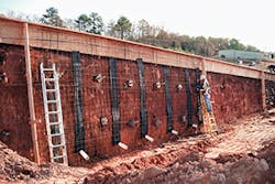
A reinforced soil wall is similar in concept and construction to a welded wire wall. As the wall is erected, form anchors are installed in the correct size and pattern to accommodate the desired form system and pour rates. Upon completion of the wall and any settlement period that may be required, the reinforcing steel and forming system are erected utilizing previously installed form anchors; 6- to 8-inch-thick fascia is then poured and stripped. The completed wall has the appearance of a non-proprietary cast-in-place wall utilizing virtually any architectural treatment that may be desired. This system is typically utilized in applications where you may encounter poor foundations causing differential settlement within the wall or in an application that may require a special or full height-architectural pattern.
Welded Wire Walls. The welded wire wall is a composite wire and granular soil structure. The wall is constructed from 9-gauge, welded steel wire fabric. The wire fabric or matting is placed between successive lifts of granular fill. The L-shaped form of the mats is designed to both reinforce the granular fill and contain the face of the structure. Welded wire walls have fewer constraints on the material or soil that can be used in the structural or reinforced volume than other wall systems. Reinforced soil retaining walls represent a new method of resolving a familiar problem. Instead of regarding soil as a mass to be contained by force, the earth itself is reinforced to become an integral part of the structure. The walls behave as gravity structures in an integral unit and provide structural flexibility. Welded wire mats placed within layers of compacted backfill provide the necessary tensile strength. Native soils at the site or from excavation are usually acceptable for backfill. The resulting structure is strong, yet resilient. The face of the wall may be built battered or vertical, left exposed, vegetated, or covered with a concrete skin or blown mortar (gunite).
Anchors. Earth anchors are driven into the ground, not augured or torqued, nor is a hole dug or drilled. There is no disturbance or displacement of soil. Many of these types of anchoring systems actually compact the soil around the anchor. The anchors are driven with conventional hydraulic or pneumatic equipment that is readily available worldwide. Once driven to the proper depth, the anchor is pulled to rotate it into undisturbed soil. Anchors are available with light to super heavy-duty holding capacities.
Tiebacks allow minimum excavation for mechanically stabilized earth walls. This allows geogrid and articulated block walls to be installed where excavation is difficult or impossible. The flexibility of most anchoring systems allows gabions to be installed on steep slopes. Anchors also stabilize embankments that are in need of repair and facilitate slope stabilization by securing geogrids, geotextiles, and fiber mats.
Soil nail and tieback retaining walls (anchored retaining walls) may have a distinct advantage over conventional walls when space is a limiting factor. The anchored retaining wall’s advantage is that it is only 12 to 18 inches wide and can be constructed without disrupting the area behind the wall. This makes soil nail and tieback retaining walls ideal solutions for constructing retaining walls in areas where space is limited.
Anchored retaining walls have an additional advantage in the stabilization of landslides. The construction of conventional retaining walls either adds weight to the driving forces of the slide or requires excavation in the toe of the slide. Neither of these actions is desirable on a slope that is already unstable. In contrast, the installation of soldier piles and tiebacks provides early and positive stabilization of the slope.
Anchored retaining walls are constructed in much the same sequence as tieback excavation support systems with the addition of corrosion protection for the anchors and a permanent wall face. The design and construction sequence of the wall must be adapted to accommodate a wide variety of wall faces. Tieback and soil nail walls are frequently faced with cast-in-place cement or precast panels. When aesthetics are important, walls can be faced with hand-laid brick or a variety of other materials.
Stability Requirements
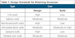
Standard designs have been developed for most of the retaining structures discussed here; these designs, often supplied by manufacturers or designers of specific types of systems, satisfy external and internal stability requirements (Table 1). Standard designs can be used in routine applications, but they must be applied with care, particularly at sites with difficult or unusual conditions.
Biotechnology and Retaining Walls
Biotechnical stabilization entails the use of live materials. Biotechnical stabilization uses mechanical elements (structures) in combination with biological elements (plants) to arrest and prevent slope failures and erosion.
Engineering principles of statics and mechanics are used to analyze and design most conventional slope protection systems, while principles of plant science and horticulture are invoked to select, propagate, and establish suitable plant materials for erosion control purposes. Geogrids, geotextiles, and welded wire are some of the structures frequently used in biotechnical designs.
Vegetated vs. Non-Vegetated
Structural facings and armor units enhance the performance of vegetation on steep slopes and sites subjected to long-duration, high-velocity flows by armoring the surface and reinforcing the vegetation. Conversely, vegetation can improve the performance of structural facings by increasing interlocking and increasing the resistance to local shear and lift-off forces.
There are many interactive processes between a plant and its soil that affect erosion. Some of these processes include the following:
- The physical binding of soil by plant stem and roots
- Electrochemical and nutrient bonding between roots and soil
- Detention of runoff by stalks and organic litter
- Improved filtration along root channels
- Greater incorporation of organic matter into the soil, resulting in better structural and water-holding qualities
- Increased faunal and biological activity, leading to better soil structure
Habitat and Aesthetics
In addition to protecting the soil against erosion from wind and water, vegetation provides habitat for birds, waterfowl, amphibians, insects, and mammals. This alone is sufficient reason to incorporate vegetation into a retaining wall design, considering the rate at which natural habitats are disappearing. Designs that include flowering or woody vegetation add aesthetic value to the project; this is especially desirable in projects built in urban areas rife with concrete.
At first glance, the “softer” types of retaining walls—those created with geotextiles, geogrids, and soil—seem to be the only versions in which vegetation can be incorporated. Most gabion walls, rock walls, and articulated block walls, however, can be designed so that a wide variety of vegetation—including woody varieties—can be used. Many versions of these typically “hard” walls create habitat by designing “step backs” in the plan. Bat aeries have become a popular habitat design in urban retaining wall designs because the bats clear the area of insect pests. Small mammals utilize the open spaces, as do amphibians and many species of birds and insects.
Conclusion
The choice of which type of retaining wall to use on a specific project site is not one to be taken lightly when such factors as footprint, loading, design limitations of manufactured materials, drainage, and soil type are concerned. When vegetation, aesthetics, and habitat creation are added to the list of decision criteria, choosing the best option becomes even more complicated.
