Largest Florida bridge build solves stormwater drainage concerns
Key Highlights
- The project utilized nearly 10,000 feet of thermoplastic HP Storm Dual Wall pipe, providing strength, joint performance, and corrosion resistance in a saltwater environment.
- Design adaptations included changing backfill material to 57 stone and modifying cross slopes mid-construction to improve drainage and reduce hydroplaning risks.
- Use of trench drains and slotted HDPE pipes effectively mitigated hydroplaning and managed runoff across multiple lanes and flat slopes.
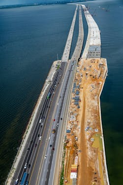
The new Howard Frankland Bridge in Tampa is the largest in Florida with more than 2.6 million square feet of bridge deck area and cost $875 million. Designing and building the stormwater drainage system for that bridge in Tampa, Florida’s largest, had to take care of 3 miles of causeway leading up to and away from the Howard Frankland Bridge, while also considering possible destructive erosion and mitigating hydroplaning. The project was successfully completed with the drainage system named Project of the Year by the Plastics Pipe Institute, Inc. (PPI), the major North American trade association representing the plastic pipe industry.
The bridge was originally built in 1960 as a single, four-lane, 3-mile span of I-275 linking Tampa to St. Petersburg. Scheduled for completion in 2026, the new bridge will have two separate roadways, each having four general purpose lanes and two express lanes. There is also a path for pedestrians and bicyclists on both sides.
One of the biggest challenges, according to stormwater design engineer, Alex George, P.E. of BCC Engineering (Altamonte Springs, Florida), “was to get a drainage system that was effective for the multi-lane causeways leading up to the bridge where it is extremely flat. During construction it was critical to keep traffic moving while grades were being changed, while keeping all drainage, including temporary systems, performing the entire time.”
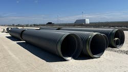
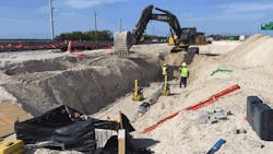
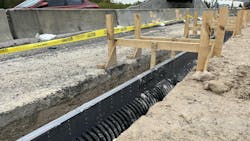
Use of thermoplastic pipe from Advanced Drainage Systems, Inc. (ADS) provided the project with a drainage system that would prevent erosion of the low-lying areas leading up to the causeways. The project used nearly 10,000 feet of the company’s HP Storm Dual Wall pipe in diameters ranging from 18 to 24 inches. Along with strength and stiffness, this polypropylene pipe also provided the required joint performance. Additionally, more than 700 feet of 12-inch diameter ADS Duraslot slotted drains, high-density polyethylene (HDPE) slotted drainpipes, were used between the express and general use lanes to handle runoff and to mitigate hydroplaning.
Both HDPE and polypropylene pipes can deal with the saltwater environment and are resilient to corrosion. Despite the aggressive environment of Tampa Bay, the corrugated thermoplastic pipes should last for decades.
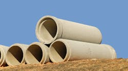
“Typically, in areas with high chlorides, reinforced concrete and metal pipe cannot be used, but thermoplastic pipe can be and will provide the required long life and resiliency,” said Daniel Currence, P.E., director of engineering for the Plastics Pipe Institute’s Drainage Division. “The two different types of thermoplastic pipe — polypropylene and HDPE with slotted drains — plus the basin drains were easily incorporated into the design-build process as each was designed to harmonically perform within the system. This aspect saved additional time, reduced labor, minimized the use of heavy equipment, creating a favorable impression for FDOT, which can be used as a benchmark for other departments of transportation.”
Currence presented ADS with the Project of the Year Award for PPI’s Drainage division during the association’s annual meeting in May 2025. Each year the PPI membership reviews and votes on Project of the Year and a Member of the Year for each of the five PPI divisions — Building & Construction, Drainage, Energy Piping Systems, Municipal & Industrial, and Power & Communications.
The ADS HP Storm pipe was also a critical component of the wall zones where there were variable height barrier walls required by FDOT to accommodate differences in elevation. Used in close proximity to the walls, the polypropylene pipe can minimize the chance of leaking that could cause erosion and affect the stability of the walls, even to the point of collapse.
“We incorporated the potential sea level rise into our drainage design, anticipating what the bay mean high water (level) might be 100 years from now, and used that as our tailwater condition,” George said. “We had to accommodate a higher tailwater for the future. We also had to be aware of the constructability of it. When we had pipes that were coming in below sea level, how we are going to build a bulkhead and a pipe through that wall and also take into consideration the stresses for the pipe?”
Most of the causeway had to be built out, according to David Alonso, construction senior project manager for the Florida Department of Transportation (FDOT). He said the team added a lot of fill material into the bay and retaining walls to hold that fill
“Then we constructed the drainage system to support additional capacity due to more surface shedding water that needs to be collected and transported without creating hydroplaning conditions,” Alonso said. “That was our challenge — adding all of the new capacity for all of that area we were building. “
Alonso continued by explaining that the team took into account how storms could affect this project. They were no strangers to hurricane season, which helped with gathering information during the construction phase and allowing for change and flexibility in the design. One such change was for the ends of the bridge, Alonso said. The typical sand material that composes backfill was converted to 57 stone, which helps improve drainage.
“During construction, we did change the design that impacted drainage due to hydroplaning conditions,” Alonso said. “We had the cross slope of the road that was shedding a little bit too much water in a certain direction, so we had to change the cross slope in mid-construction, which triggered a lot of a lot of changes to the drainage system such as the inlets and sizing of the pipes. That’s something to consider when adding so many new lanes to a roadway and trying to tie that into an alignment that's existing is how much water is shedding off the surface.”
George further explained the drainage benefits.
“We used the trench drain as a way to mitigate hydroplaning risk for the project, especially in areas where there are a number of lanes, plus we had flat slopes — it’s a lot of pavement to deal with,” he said. “That sheet flows across a lot of lanes, which has the potential to cause hydroplaning issues, and we worked closely with FDOT District 7. We did a detailed analysis of at least 50 locations along the project to analyze what would and would not work from a hydroplaning risk perspective. Using trench drain in areas, sometimes in between the express lanes and the general use lanes to pick up that runoff before it drains across another set of lanes was the tool we use to mitigate that risk.”
George also said that the ADS pipe is not subject to corrosion and therefore “checks a lot of the boxes for an aggressive environment like this.” For some sections of the project, George said, the team used barrier walls or other forms of wall to accommodate a difference in elevation. FDOT requires the use of wall zone pipes.
“Those are pipes which are allowed to be used in close proximity to the walls that minimize the chance of leakage or affecting the stability of the walls or collapse,” he said. “For those particular areas there's a limited choice of available pipes that can be used, and the ADS pipe passed the test. FDOT, naturally, wants to avoid future issues with other types of pipe, especially if leaks were to reach MSE wall, backfills or underneath the variable height barrier walls with footers. We had to be very careful about where we could put pipes and which pipes would be effective in these locations and ultimately approved.”
At a time when sustainable infrastructure is heavily discussed, this project offers modern solutions.
“As Florida and our country continue to invest in transportation projects to ensure our infrastructure’s future,” Currence said, “this project shows how forward-thinking design and proven products can solve today’s modern stormwater challenges. The Howard Frankland Bridge stands as a benchmark for what’s possible when agencies, engineers, and manufacturers work together with long-term performance in mind. With resilient materials and strategic planning built into every phase, this FDOT bridge is prepared to serve the region for decades to come.”